Relatively small in size, infrared (IR) warns locator the sound signal of the approach to any obstacle (wall, fence) or object. The signal appears at a distance to the obstacle is about 1.5 m, and at least further the frequency of the signal increases smoothly.
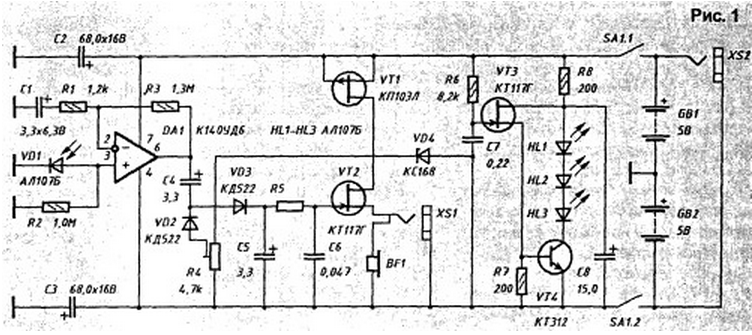
Diagram of the locator shown in Fig. 1.

Led VD1 and the assembled chip DA1 receiver infrared radiation and an amplifier, the transistor VT2 - driven generator of audio frequency, and the transistors VT3, VT4 and LEDs HL1 HL3... - in IR transmitter.
Review of radar operation will start with the transmitter. On the VT3 transistor is assembled the generator of short pulses, following with a frequency of about 1000 Hz. After charging capacitor C7 voltage 5...6 In a rapid discharge through VT3 transistor and the emitter junction of transistor VT4. In this case, the transistor VT4 open, and through it flows and LEDs the current pulse, as a result which appears a pulse of IR radiation.
Reflected from the object IR pulse gets on receiving the led VD1 and converts them into an electrical signal, which is then fed to the amplifier, collected by operational amplifier (op-amp) DA1. The amplified signal is fed to the rectifier is performed on the diodes VD2, VD3 scheme-doubling (addition) voltage. The rectified signal smoothed by capacitor C5 and fed to a controllable oscillator CC. If the subject distance is more than 1.5 m, the power of the reflected IR radiation, and hence the voltage at the input of the controlled oscillator - emitter transistor VT2 is not enough for it to work.
When the distance decreases, the level of the reflected signal increases, and the generator AF starts. Moreover, the greater the reflected signal, i.e. the closer to the reflecting object, the faster the charging capacitor C6 and the higher the oscillator frequency. As a sound emitter used compact the headset BF1. The threshold generator is adjustable trimpot resistor R4.
For more precise operation of the generator and its stable operation of power the generator is fed through a parametric voltage regulator transistor VT1 and the Zener diode VD4. In General, the locator is powered by batteries GB1 and GB2, each them consists of four series-connected batteries D-0,06. To the locator you can connect an external telephone through the connector XS1, internal telephone when this is disabled.
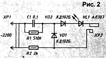
For periodic recharging of batteries in the locator provides a connector XS2, which include the plug from the charger, harvested by appearing on Fig. 2 scheme.

HL1 led in it indicates battery charging. Capacitor C1 should be paper for a rated voltage of not lower than 400 V, and the diode - rectifying any with a maximum reverse voltage of 300 V.
In the operation of the locator should be remembered that it responds to IR radiation lighting incandescent lamps at a distance of several meters.
Author: I. Nechaev, Kursk


