For the effective suppression of the harmonic components often use lowpass filters (LPF), connected to the output of the transmitter. Such a filter without substantial attenuation to pass frequencies up to 30 MHz and significantly weaken the signals of higher frequencies. Its input and output resistance should be consistent with the wave impedance of the feeder line. The number of parts of the filter is chosen depending on the required size of the suppression of spurious emissions.
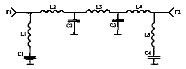
According to CCIR recommendation and the requirements of GOST, the average power of any spurious emission supplied to the feeder must be 40 dB below the average power of the main signal but not exceeding 50 mW [1]. Therefore, a sufficient degree of suppression of spurious emissions in the radio stations with input power up to 200 watts it will provide pjatizvennye the filter, the degree of suppression of which is determined by the formula: b=10lg(P1/P2):n where Pi is the power output; P2 is the power input; n is the number of parts of the filter. Pjatizvennye filter, the circuit of which is shown in Fig.1, was proposed by S. G. Bunin, L. P. yailenko [2].

Fig.1
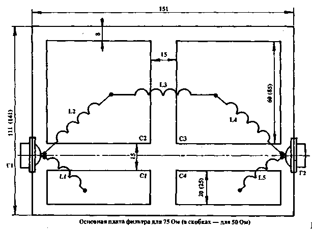
He has not received proper recognition due to the fact that the authors presented the brand of the used electronic components and data on the size and technology of the filter. The proposed technology of manufacture of such a filter is quite simple and does not require for the manufacture and customization of large experience and scarce parts, and special tools. She's quite a force to novice radio Amateurs. Structurally, the filter is made in a box of two-sided foil fiberglass 1.5 mm thick (use other fiberglass thickness is undesirable because of the change permanent filter tanks). Box height is not critical and in this case equal to 40 mm. On the main Board (Fig.2), which is the bottom of the box, using cut or etching to form a plate of a foil according to the specified sizes for 75 Ohm cable (in parentheses are the dimensions for 50 Ohm cable).

Fig.2
These plates form a precisely tuned filter capacitors.
Contour coil are made of ordinary copper wire PEV-2 in diameter of 2.0 mm. Winding frameless. The inner coil diameter is 12.5 mm. Step of winding is 3 turns/cm (i.e., L-2 cm, etc.). The filter parameters are given in table. 1.
Characteristic impedance of the cable
C1, C4 pF
C2. C3
L1,L5
L2,L4
L3
revolution.
mcg
hall K.
mcg
revolution.
mcg
50
50
170
3.5
0.15
8
0.32
9
0.36
75
40
120
6
0.27
11
0.44
13
0.66
The coils are soldered to the connectors and to the plates of capacitors. The soldering is not critical. Connectors G1 and G2 - type SR-50, SR-75 and the like. You can use the filter and without connectors, including it in a cable breaking. In this case, the coil connector is mounted on the insulator and soldered core of the wire. The braid is threaded inside the box, raspivaetsya on the perimeter. When properly designed, the size of the filter requires no configuration. It should be noted that the filter does not eliminate interference caused by bad contact of the antenna and feed line. Experimentally, the filter is checked for random antennas fed by a coaxial cable with a substantial SWR and power output over 200 watts. Interference to the TV was missing. This filter is repeated over hundreds of radio Amateurs. Without configuring it showed good results.
Literature
1. "Radio", No. 10, 1983, pp. 17-20.
2. S. G. Bunin, L. P. Yailenko. The radio Amateur's Handbook-the shortwave. Kiev.: Appliances, 1978, p. 190.
3. "Amaterske radio", No. 5-6, 1976
Author: A. Ronzhin, Vladimir region, Petushki; Publication: N. Bolshakov, rf.atnn.ru


