The point is probably that earlier in the USSR, almost all used a homemade tube-like instrument, the output stage can coordinate with almost anything.
Transistor RA reveals much more harmonics than the tube. And often nizkodobrotnoi P-loop output transistor RA cannot cope with their filtering. Besides, we must remember that the number of channels compared to what it was even a few years ago, has grown many times over!
The purpose of matching device
SU provides the transformation of the output impedance of the transmitter to the antenna impedance. Use SU with a tube amplifier having a P-loop with all three continuously tunable elements, irrationally, as a P-loop ensures harmonization in a wide range of output impedances. Only in cases where the elements of the P-loop will eliminate the adjustment, use the SU benefits.
In any case, SU markedly reduces the level of harmonics and its use as a filter is justified.
When good-minded resonant antennas and good RA no need to use a matching device. But when one antenna operates at multiple ranges, and RA does not always give what we need, use SU gives good results.
The principles of matching device
Classic SU is shown in Fig. 1. As can be seen, it consists of a chain of approval (CA), which is made by one of the known schemes (actually CA often and is called "matching device", "ATU"), SWR meter, RF bridge, showing the degree of misalignment of the antenna, dummy R 1, and target load R2, R3. Without all of this "environment" SU is only a chain of approval, nothing more.
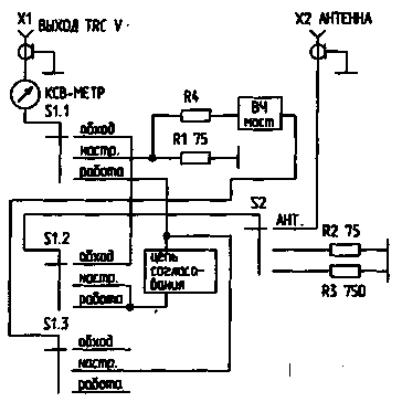
Fig.1
Let us examine the principle of operation of the device. In S 1 "Bypass" output of the transmitter connected to S2, which gives the opportunity to either directly connect the antenna or switch to one of the output load equivalents (R2 or R3) and to check the possibility of harmonizing the transmitter with him. In the "customize" the transmitter operates on a matched load. Also through resistance R4 turns on the RF bridge. For the balance of the bridge circuit approvals and carry out the adjustment of the antenna. Resistors R2 and R3 provide an opportunity to check if it is possible to configure the chain of approval on them. Configuring the CA include the "run" mode. In this mode a little more adjust chain agreeing on a minimum readings on the SWR meter.
Below are used to practice basic CA.
Chain coordination in a parallel circuit
One of the most effective and simple doable CA shown in Fig.2. The transmitter is connected through the coil L1 and the capacitor C1. L1 is between one quarter to one sixth of the number of turns and L2 is wound in its lower part. L1 should be separated from L2-quality insulation.
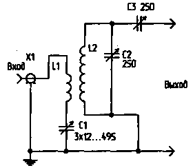
Fig.2
In this scheme, the transmitter is associated with the CA, only the magnetic flux, and here automatically solved the problem of lightning protection of the output stage. The capacitor C1 for operation at 1.8 MHz. must have a maximum capacity - 1500 pF, and for the 28 MHz to 500 pF. C2 and C1 should have the largest possible gap between the plates. The range of load resistances from 10 Ohms to several of the shortfall. Work with high efficiency is provided in two adjacent bands, such as 1.8 and 3.5 MHz. To work effectively in several ranges to be switched L1 and L2. At small power (up to 100W) most effectively and simply make a set of replacement coils and permit installation with ground panels from old radio tubes. Any experiments associated with connecting in parallel L1 and L2 coils to reduce their inductance for operation on HF bands, connecting to the taps of these coils are tricky parallel connection of the coils significantly reduce the effectiveness of this CA on HF. These coils for circuit of Fig.2 are shown in table.1.
Table.1
Range, MHz
1,9
3,5 3,8...
7
10
14
18
21
24
27 30...
Diameter of coil, mm
50
30
25
25
25
25
25
25
25
The length of the winding, mm
50
30
40
40
40
40
30
30
30
Number of turns
100
30
20
15
11,5
10
8,5
7,5
6,5
Although currently symmetric antennas are rarely used, consider the work of this CA is symmetrical load (Fig.3).
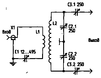
Fig.3
Its only difference from the circuit of Fig.2 in that the voltage for the load is removed symmetrically. L1 should be located symmetrically with respect to L2. The capacitor C 1 and C2 must be on the same axis. It is necessary to take measures to reduce the influence of the capacitive effect on L2, i.e. it must be located far enough away from the metal walls. Data L2 for the scheme of Fig.3 are given in table.2.
Table.2
Range, MHz
1,9
3,5 3,8...
7
10
14
18
21
24
27 30...
Diameter of coil, mm
50
40
25
25
25
25
25
25
25
The length of the winding, mm
60
40
40
50
40
40
40
40
35
Number of turns
130
35
28
20
15
11,5
11
9,5
8,5
Meet and design a simpler version of this CA.
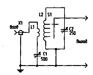
Fig.4
In Fig.4 shows a single-ended circuit in Fig.5 - symmetric. But, unfortunately, experience shows that these schemes can not give such careful coordination, as in the case of using the capacitor C3 (Fig.2) or C3.1, C3.2 (Fig.3).
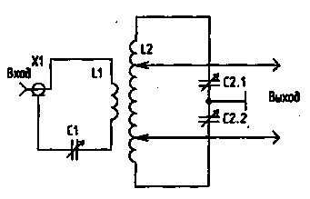
Fig.5
Especially carefully it is necessary to approach the construction of a multi-band CA operating on this principle (Fig.6). By reducing the quality factor of the coil and large capacity taps "on the ground" the efficiency of such a system on HF bands is low, but the use of such a system in the range of 1.8...7 MHz is acceptable.
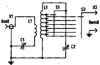
Fig.6
Configure the CA shown in Fig.2, just. The capacitor C1 is put in the maximum position, and C2 C3 - minimal, then using a C2 tune the loop to resonance, and then, increasing communication with the antenna using C3, achieve maximum return power to the antenna, all the while adjusting C2 and C1. You should strive to ensure that after you configure the CA C3 had a maximum capacity.
T-shaped chain coordination
This scheme (Fig.7) is widespread when dealing with unbalanced antennas.
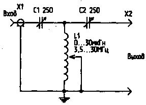
Fig.7
For normal operation this CA required continuous adjustment of the inductance. Sometimes even half-loop is crucial for reconciliation. This limits the use of inductors with taps or requires individual selection of the number of turns for a particular antenna. It is necessary that the capacitance of C1 and C2 to ground was not more than 25 pF, otherwise it may reduce the efficiency by 24...28 MHz. It is necessary to "cold" end of the coil L1 was thoroughly grounded. This CA has good parameters: efficiency - up to 80% of the transformation from 75 Ohms to 750 Ohms, the possibility of balancing the load of 10 Ohms to several of the shortfall. Using only one variable inductance 30 mH can cover the entire range from 3.5 to 30 MHz, and connecting in parallel with C1, C2 constant capacitors of 200 pF, possible to work at 1.8 MHz.
Unfortunately, the variable inductance road and structurally complex. W3TS proposed switchable "digital inductance" (Fig.8). Using such inductance, using switches, you can clearly set its value.

Fig.8
Another attempt to simplify the design has taken firm AEA by performing the matching device according to the scheme shown in Fig.9. Indeed, the scheme in Fig.7 and Fig.9 are equivalent. But structurally it is much easier to use one high quality grounded capacitor instead of two isolated and expensive variable inductance replace with a cheap fixed inductors with taps. This CA worked well from 1.8 to 30 MHz, transforming 75 Ohms 750 Ohms and 15 Ohms. But when working with real antennas are sometimes affected by the discreteness of the switch inductance. In the presence of 18, and preferably 22 positional switches this CA can be recommended for practical implementation. Thus it is necessary to minimize the length of the taps of the coil to the switch. Switches 11 AEA at-30 TUNER L1-L2-25 Turns, dia. coil 45 mm winding pitch of 4 mm taps from each coil along the length of 10 turns then after 2 revolution of the provisions give the opportunity to make a CA-only work on part of the Amateur bands from 1.8 to 7 or 10 to 28 MHz.

Fig.9
The coil is structurally convenient to perform as shown in Fig.10. Frame it is a plank of the bilateral fiberglass with the cuts at the turns of the coil. This strap is equipped with a switch (for example PN). The taps of the coil go to the switch on both sides of the glass fibre laminate planks.
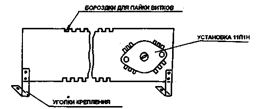
Fig.10
When working with symmetrical antennas together with the T-shaped matching unit use voltage-balun 1:4 or 1:6 on the CA exit. This decision cannot be considered effective since many symmetric antennas have a large reactive component, and the transformers on ferrite very poorly in reactive load. In this case, you must apply measures to compensate for the reactive component or to use a CA (Fig.3).
U-shaped matching circuit of
U-shaped CA (or P-loop) whose schema is given in Fig. 11, widely used in Amateur practice.
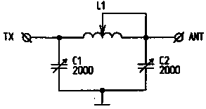
Fig.11
In real conditions, when the output of the transmitter is 50...75 Ohm, and coordination must be made with a wide range of load resistances, the parameters of the P-loop are changed dozens of times. For example, 3.5 MHz at Rin=RL=75 Ohms inductance L1 is approximately 2 mH, a, C1, C2, and 2000 pF, when Rin=75 Ω and RH in some of the shortfall of the inductance L1 is about 20 μh, the capacitance C1 of about 2000 pF, and C2 - tens of picofarads. Such large variations in the values of elements used and restrict the use of P-outline, CA.
It is desirable to use a variable inductance. The capacitor Cl may have a small gap, and C2 must have a clearance of at least 2 mm on each 200 watts of power.
Improving the efficiency of matching device
To increase the efficiency of the transmitter, especially when using random antenna helps a device called an "artificial ground". Effectively this device when using random antennas and in poor radio ground. This device brings to the resonant condition of the earthing system of the station (in the simplest case - a piece of wire). Since the parameters of the earth are included in the parameters of the antenna system, improving the efficiency of earthing improves the performance of the antenna.
Conclusion
Matching device should be used no more often than it really should. You should choose the type SU you need. For example it makes no sense to produce a broadband device for operation in the range of 1.8 to 30 MHz, if you really don't "built" antenna 1...2 range, or for these ranges are used surrogate antenna. Here's much more efficient to perform on each range its own individual SU. But of course, if you are using a transceiver needsdriven output, and most of your antennas - surrogate, then it is essential sidepane SU.
All of the above applies to the device "artificial ground".

Fig.12
Literature
1. Podgorny, I. (EW1MM). RF grounding/ LW Radio Amateur and УSW. - 1995. - No. 9.
2. Grigorov I. (RK3ZK). Matching device on coaxial cable/ Ham. - 1995. - No. 7.
3. Podgorny, I. (UC2AGL). Antenna tuner/ Radio Amateur. -1994.-No. 2.
4. Podgorny, I. (UC2AGL). Antenna tuner/ Radio Amateur. -1991.-No. 1.
5. Grigorov I. (UZ3ZK). Universal matching device// Amateur Radio operator. - 1993. - No. 11.
6. Padalko S. (RA6LEW). Antenna switching interface device/ Radio Amateur. - 1991. - No. 12.
7. Orlov V. (UT5JAM). Sidepane matching device to LW/ Hams. -1992. - No. 10.
8. Velleman P. (F9HY). Matching device for antenna type LEVY/ /Amateur Radio operator. - 1992. - No. 10.
9. Podgorny, I. (EW1MM). Universal antenna matching device/ Radio Amateur. - 1994. - No. 8.
Author: I. Grigorov (RK32ZK), Belgorod; Publication: N. Bolshakov, rf.atnn.ru


