


")

Beginner ham radio is a very popular variety of "flashers" - generators light pulses. They can be installed on baby toys, to use in your rides, post in a conspicuous place in the vehicle for simulate the action of a watchdog device. With some variation of such devices introduces the proposed collection.
… with triacs
Relatively simple "flashers" are obtained when using triacs. However, a feature of most of triacs is that they open when applying to the control electrode of a certain voltage (current), as for them closing it is necessary to reduce the anode current to a value below the current hold.
If to nourish the SCR of the AC or pulsating voltage, it will automatically be closed when current flows through zero. When powered same DC voltage SCR just closed will not, have to use special technical solutions
The scheme is one of the options "flashers" on the triacs shown in Fig. 1.
The device comprises a generator of short pulses at one-transition-effect transistor VT1 and two cascades on the triacs. In the anode circuit of one of the triacs (VS2) included incandescent lamp EL1.
Device works well. At the initial time after power-both SCR closed and the lamp is not lit. The generator produces powerful short pulses with the interval defined by the chain R1C1. The first stage will go on control electrodes of the triacs, and they will open. The bulb lights up. Due to the current flowing through the lamp, SCR VS2 will remain open, but the VS1 closes, as its anode current determined by the resistor R2, is too small. The capacitor C2 starts charging through the resistor and by the time you receive the second pulse generator would be charged. This momentum will lead to the gate of SCR VS1. and left circuit output capacitor C2 will be momentarily connected to the cathode of SCR VS2. But even with that connection enough SCR closed and the lamp went out.
Thus, both the SCR will be closed, the capacitor C2 is discharged. The next pulse generator will lead to the opening of the triacs, are described the process will be repeated. The lamp flashes with a frequency twice the frequency generator.
For these in the scheme of items you can use an incandescent lamp (or some lamps are connected in series or in parallel) with current up to 0.5 A. If you use all capabilities of these triacs, it is permissible to apply the lamp, which consumes current up to 5 A. In this case, for secure closure the SCR VS2 capacitance of the capacitor C2 should be increased to 330…470 µf. Accordingly it is necessary to increase the capacitance of the capacitor C1, so that in the periods between the pulse generator, the capacitor C2 have time to charge. SCR should VS2 to put on a small heatsink.
The details of the "flashers" are mounted on a printed circuit Board (Fig. 2) from unilateral foil Micarta or fiberglass. Oxide capacitor C2 definitely aluminum, series C50-6. K50-16, K50-35.
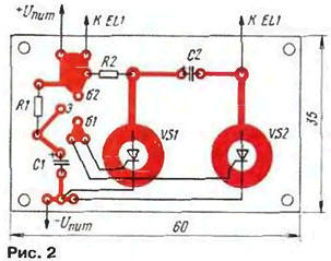
If the lamp current exceeds 0.5 A, one of the triacs can be replaced low-power, for example, COA (Fig. 3).
Since the voltage on control the electrodes of the triacs in which they are opened, various, device introduced trimpot resistor R2, which select the optimum mode of their work. In addition, increase the resistance of the resistor (R3) in the anode the SCR VS1.
Parts of the device are placed on a printed circuit Board (Fig. 4) foiled material.
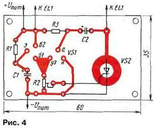
The establishment of structures is reduced to the setting of the desired frequency "flicker" bulbs the selection of the capacitor C1. If the bulb lights up but does not go out, so either SCR VS1 is not closed (it is necessary to increase the resistance resistor R2 in the first "flasher" or R3 in the second), or does not have time to recharge the capacitor C2. Then it is desirable to reduce its capacity, and even better - the frequency switching. In the second "flasher" you need to install the engine tuning a resistor in a situation in which work steadily both SCR.
… with two-color LEDs
About two-color LEDs (also called dwukrotnie) were described in product sheet "Dwukrotnie light-emitting diodes" in "Radio". 1998. No. 11, p. 57-60; 1999, No. 1, pp. 51-54. They can find wide application in a number Amateur radio designs. Here, for example, the generator (Fig. 5), which can to serve as an overload indicator, alarm modes. It's easy to embed in the corresponding electronic device. In it. in addition to two-tone LEDs HL1, used chip structures TTL (hook up).
The basis of design - the pulse generator is assembled logic elements DD1.1. DD1.2. With the generator connected to the cascades on the elements DD1.3. DD1.4. To them the outputs are connected (via current-limiting resistors R2 and R3) two-tone led. When applied to the control input (pin 1 of the element DD1 .1 ) low logic level the generator will not work, and at the exit of the element DD1.3 established high level, and the output DD1.4 - low. Lights up on the right the scheme crystal led HL1. Light color can be red or green, in depending on how to connect the led (if specified in the scheme version the inclusion of the conclusions of the color will be red).
If this generator to use as an indicator of an emergency, right the crystal should be green, and its glow will indicate normal operation the controlled node.
In the case of receipts for the control input (e.g., when there will be fault) logic high generator will begin to robogate. Pulses will go on the logic elements DD1.3, DD1.4, their condition will become alternately to change, and the led will change the color of your glow with a repetition rate of pulse generator.
Is defined in the diagram is permissible to apply the same chip series K155. 530. C. KR531, 533. K555.1553, KR1533 and other chip structures TTL or hook up (except items with an open collector). Trimmer - SDR, constant - MLT, S2-33. capacitor - C50-6, K50-16.
Establishing device is to install a resistor R1 of sustainable generating at minimum frequency. The desired pulse repetition rate can to set the selection of the capacitor. To change the color of the glow were visible, this frequency should be no more than a few Hertz. The brightness of the LEDs it is possible to increase the selection of resistors R2, R3 of least resistance.
In this device used two-color LEDs with separate findings from crystals. If you use LEDs with a counter-parallel (with two conclusions) KIPDA-CIPD or any of a series of CIPD, the scheme had to be changed in accordance with Fig. 6.
To ensure that the led does not change color of its illumination, and the short-term flashed by turns a different color scheme had to be changed in accordance with Fig. 7.
In this embodiment, when the appearance of the high level at the outputs of the elements DD1.3, DD1.4 will charge in the capacitor C2 and will flash briefly left the scheme crystal led. When will the low logic level, the capacitor will be discharged, catching the right crystal. The selection of the capacitor C2 achieve the desired duration of outbreaks.
Diagram of the generator of light pulses on a chip of the CMOS structure shown in Fig. 8. Since this chip has a low load capacity, for matching the generator performed on the elements DD1.1 .DD1.2. and buffer element DD1 .3 with led HL1 in the device entered the transistors VT1, VT2. Here, the generator is also accomplished by supplying the output 1 item DD1.1 logic levels. At low level, the generator is not working, lights up right under the scheme the crystal led. When goes to a high level, the generator is activated, the color of the led changes with frequency pulse generator.
The oscillator frequency is roughly set selection of the capacitor C1, and a smoothly resistor R1. Brightness set selection of resistors R2, R3.
In this generator, the elements work well most of microcircuits CMOS structure (except for items with open-drain). Transistors - any of a series of KT315, KT3102, capacitor C1 - K10-17, K73, MBM, C2 - C50-6, K50-35, K52, resistors such same as in the previous generator.
For LEDs with a counter-parallel radiating crystals in schema it is necessary to change in accordance with Fig. 9. The selection of the capacitor C3 can be set the different operation mode of led: when increasing the capacity of the glow color will change abruptly; but if it be reduced, there will be a short flash with alternate color-changing glow. More smoothly mode set selection resistor R2.
Transistors - any of these in the scheme of series. Other details - such as types as in previous designs.
Author: I. Nechaev, Kursk