Many hams there are various radio components of issue of the past. From you can pick quite a good lab power supply unit (PSU) with protection from overload and short circuit and also to test and adjust the homemade products. The author of this PSU works since 1983 without a single failure. Details on this PSU also to buy on the cheap at radio.
Technical data BP
- Uвых = 0,5...30 V (0.5 To 15 In; 9-30)
- SAS = 0.7 A
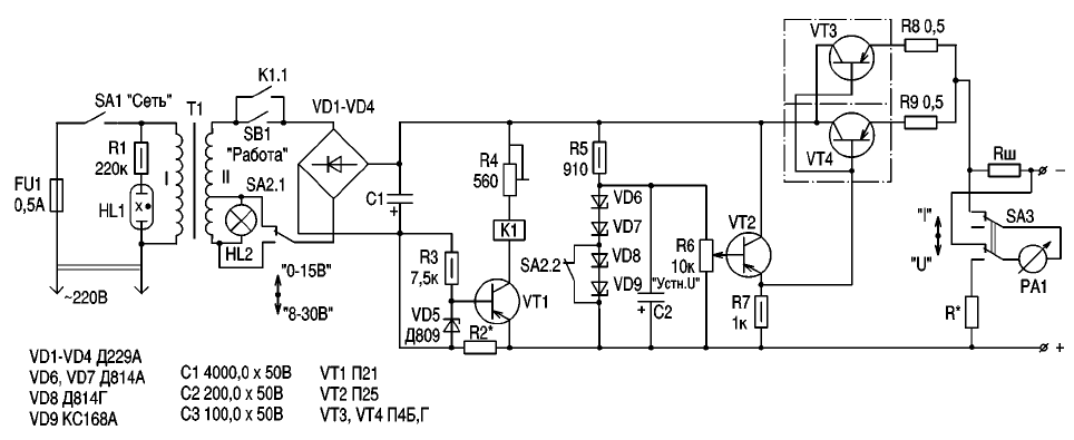
Consider the operation of the circuit of power supply (see figure).

(click to enlarge)
When you switch SA1 ("Network") voltage 220 V is applied To transformer T1. Lamp lights HL1, indicating the flow 220 In the primary winding of the transformer T1. Also lights up HL2 covering the scale of the instrument RA1. This suggests that the secondary winding of T1 the tension is removed. When you press the button SB1 ("Work") the voltage from the secondary winding of T1 is fed to rectifier bridge VD1-VD4 and with him - on the BP scheme. When this triggers the relay K1 and its contacts K1.1 locks the button. The button can to let go of.
BP starts to work. Relay K1 is actuated, as VT1 is open. Scheme the voltage regulator has no peculiar features. A voltage regulator built according to the classical scheme of compensatory type. Therefore, his work will not stop. Consider the operation of the circuit overload protection and short-circuit.
All the current consumed by the load flows through the resistor R2*, creating it a specific voltage drop that is applied to transition B-e of the transistor VT1 through the Zener diode VD5. At a certain current the voltage drop across R2* exceeds the breakdown voltage of the Zener diode, and a transistor VT1 is closed. The relay is de-energized and the contacts K1.1 is open. Scheme PSU de-energized. Next, switch the PSU to the "run" mode is possible only when you are Troubleshooting faults in the connected device.
The selection of the resistor. R2* can be adjusted current protection operation. The instrument PA1 output controls the voltage of the power supply and consumed by the load current. The resistance of the shunt and Rш additional resistor R* to control the output current and voltage adjust depending on the chosen device. The author used the device type RM-70.
For easy operation the device is mounted lighting bulbs scale HL2. For control the inclusion and presence of voltage 220 In the primary winding of T1 is indicator neon lamp HL1. If desired, the bulb can HL1 and HL2 replace the LEDs when the corresponding switching circuit. Such schemes repeatedly printed in various electronic publications.
Using SA2 selectable output voltage range of 0.5-15 and In 8-30 V. Instead of those details you can use any other similar parameters.
The Transformer T1 any power of 35 watts with two secondary windings and the voltage 22-25 In each providing the load current is less than current protection operation.
The author used transformer type CCI 268-220-50K. Transistors VT3 and VT4 are the radiators of ~100 cm2. They can be installed on a common heat sink. Relay K1 type RES 9 (passport 200). The transistor VT2 for reliability, you can also place on a small heatsink.
Author: O. G. Rashitov, Kiev


