When using a quartz resonator with a high frequency becomes possible to create
a simple radio microphone with a high stability of the carrier frequency. Below is a description of such devices.
The microphone works in a range 61-74 MHz with frequency modulation.
A schematic diagram of a transmitter of a radio transmitter are shown in figure 13. The signal from the microphone M1 type FEM-3 is amplified by two-stage amplifier transistors VT1, VT2 type CT. The master oscillator is made on the VT3 transistor type KT368. Frequency modulation of the carrier frequency provided by the variable capacitor VD2. Resistors R6 m R7 in the base circuit of the transistor VT3 determine its mode DC. Capacitor C9 sets the mode of generation, providing positive feedback. The frequency stability of the generator depends mainly on supply voltage. To improve, you need to use a stabilizer In 6-9 that will lead to more complex schemes. To stabilize the frequency in another way. To be precise, the instability of the carrier frequency is determined mainly by fluctuations in the operating point of the transistor VT2 amplifier audio frequency when you change the voltage. The position of this operating point determines the reverse voltage of mixing on the varicap VD2, and thus its initial capacity. To stabilize the operating point of the amplifier transistor VT2 in its base circuit a resistor R4, the voltage of which is supplied with parametric stabilizer collected on the resistor R2, diode VD1 and the capacitor C1. In the device used fixed resistors MLT-0,125, capacitors types K50-16 and km. Chokes DR1, dr2 do you can use the standard, for example, type D-0,1, inductance 15-30 mH or make yourself. Chokes are wound resistors MLT-0,25 a resistance greater than 100 ohms and contain 50-60 turns of wire sew 0.1 mm. Contour coil L1 wound on the frame with a diameter of 8 mm and consists of 6 turns of wire sew 0.8 mm. Coil L2 wound on the same frame and the same wire as the coil L1. Coil L2 contains 3 coils placed at a distance of 1 mm from the turns of the coil L1. The antenna is made as follows: cut a 50-Ohm cable length of 10-12 cm trimmed the insulation and the metal core is removed. Across the cut length of the cable is wound round the wire sew-0.6 - antenna ready. In an extreme case as an antenna, you can use a wire with a length of 30-50 cm Configuration start with the audio frequency amplifier. The change of the resistance of the resistor R4 sets the voltage at the collector of transistor VT2 equal to half the voltage of the power supply. The capacitance of the capacitor C9 should be selected according to the maximum current consumed by the generator, and then the resistor R6 to set this current is about 10 mA.
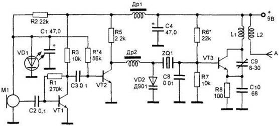
Figure 13. The radio transmitter with a high stability of the carrier frequency.


")
