In operation there are a lot of television receivers color image (TPCI), which are designed to work with audio amplifier intermediate frequency (the PDDH) CCIR (the symbol B, G) and the spacing of the carrier frequencies of the sound and image of 5.5 MHz. The same applies to many older VCRs. We have adopted a standard OIRT (the symbol D, K) with the difference of carrier frequencies for the image and sound 6.5 MHz. In order for these devices can be used we require alteration of the block of the PDDH.
There are several ways of remaking the PDDH channel
1. Used provided equipment will be operated only in standard OIRT. Only need a restructuring of the inductance of the circuit with the PDDH frequency of 5.5 MHz to a frequency of 6.5 MHz; this can be done by unscrewing the ferrite core. However, this is not always possible, and sometimes necessary to reduce the capacitance of the capacitor of the inverter circuit in the PDDH. Since cascade of sound TV used piezoceramic filters, they should, accordingly, be replaced by 6.5 MHz.
2. The installation of the PDDH, designed to an appropriate standard;
however then still need a device for automatic recognition of audio standards. However, it is possible and easy to switch standards sound with a normal switch.
3. Using audio consoles-Converter, which is actually a local oscillator and a mixer. Generator Converter consoles usually tuned to the frequency of 1 MHz or 12 MHz. In the first and the second cases, the turns spacing 5.5 MHz, which is processed by the PDDH. This method is very simple and extremely convenient.
Now consider a schematic diagram of the sound Converter with a reference signal frequency of 1 MHz (Fig.1). This BOF console consists of an input bandpass amplifier VT1, which is loaded bandpass filter consisting of parallel piezoceramic filters ZQ1 and ZQ2, and also from the amplifier-mixer (transistors VT2 and VT3) and a reference signal generator implemented on VT4 and ZQ3 that are enabled by three-point capacitive scheme. The console has a relatively high sensitivity and high gain. It can be used in a number of production models of TVs and VCRs with tuners firms ATWA, NEC, JVC, SAMSUNG, etc. the Resistor R4 is chosen empirically depending on the type used piezoceramic filters with three pins.
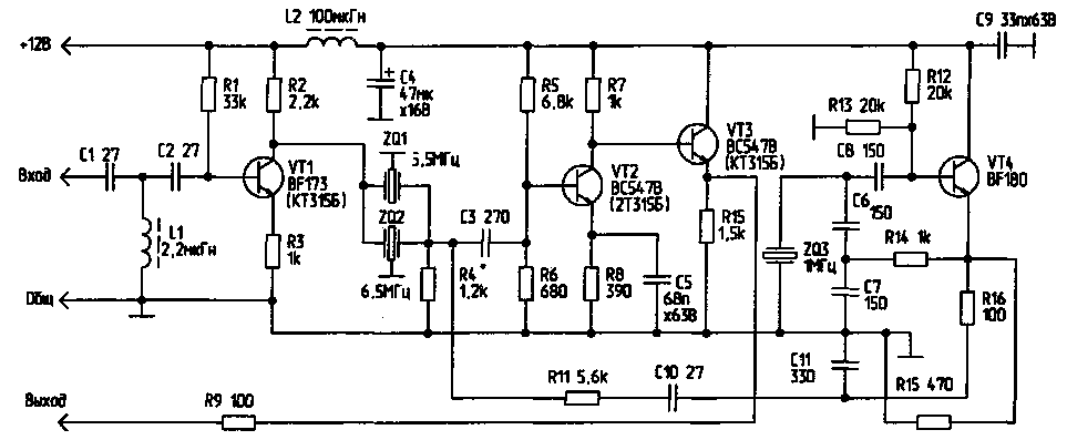
Fig.1 (click to enlarge)
The circuit shown in Fig.1, is quite complex, and the reference signal frequency of 1 MHz can fall into the bandwidth of the signal that will lead to the emergence of a "moire" on the screen. This significant drawback devoid of the Converter box with the signal generator frequency is 12 MHz. The reference signal of this frequency is not within the bandwidth of the video signal, so that interference is eliminated.
There are two options for connection of the Converter STB to the TV receivers and VCRs is to interrupt the path of sound frequencies and without such interruption.
Diagram of a Converter box that is activated by interrupting the path of sound frequencies, is shown in Fig.2. The generator is implemented as a circuit with inductive feedback and input bandpass filter consists of two or three piezoceramic lead high efficiency filters. This console can connect to the TV, working on OIRT (6.5 MHz) and CCIR (5.5 MHz), when the gap signal paths must be performed before the input filter of the audio signal of the TV.
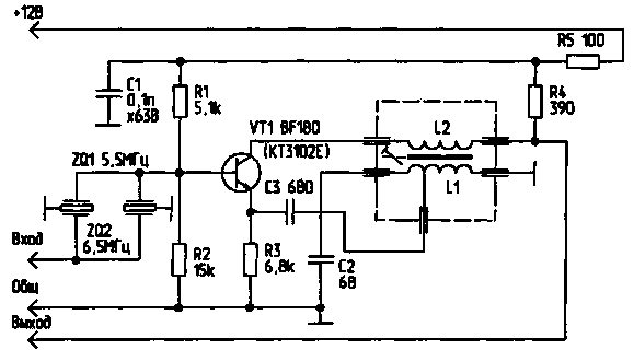
Fig.2
The inductors L1 and L2 are wound on the finished frame, taken from the defective module SMC-2 from ZUSTST type "Electron 380", "Photon 381", "Electron 382", etc; also used their cores and screens. The inductance L1, which is used for communication has a 4+12 turns of wire PEL of 0.12, and the coil L2 has 12 turns of the same wire. L1 and L2 are located at a distance of 3...4 mm from each other. Setting the schema is simple - rotating core is necessary to achieve the most loud and clear sound. In Fig.3 shows the printed circuit Board and the location of parts on it.
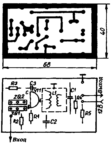
Fig.3
In Fig.4 shows the latter scheme, the most convenient for professional and Amateur the implementation of the Converter audio consoles. It is an auto-generating mixer with the frequency of the reference signal is 12 MHz.
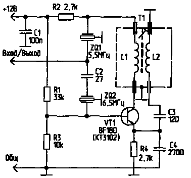
Fig.4
There's no need to break the link between UPCI image intermediate frequency and UPSC . Transformer T1 is wound on armored core from radio's"Falcon" or from any other transformer of the inverter. The inductance L1 has 12 turns of wire PEL 0.1, L2, is used to communicate, has 3 coils of the same wire. Output ceramic filter if necessary can be replaced by ZQ2 - console is universal for both standards.
In Fig.5 shows a printed circuit Board and the wiring diagram of the Converter. L1 and L2 located from each other at a distance of 3...4 mm. schema settings - elementary, and is similar to setting the prefix, as shown in Fig.2.
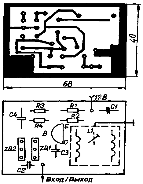
Fig.5
All the above consoles are experimental. In my experience, the highest quality have the last two. Prototyping valuable assistance rendered me engineer D. Georgiev and engineer A. Andreev from "TU-Sofia.
Literature
1. Radio, television, electronic gadgets, 1993, No. 7,8.
2. Ham, 1992, No. 1-3.
3. Radio, television, electronic gadgets, 1997, No. 11, 12.
Author: D. Kostov, Translated By A. Wolski; Publication: N. Bolshakov, rf.atnn.ru


