


")

A defect of the volume controls in radio encountered, probably many of its users. To eliminate this disadvantage by applying the original solution, which are explained in the material published here.
The volume control in home appliances wear out more frequently than other parts. In dynamic heads appear rustling, crackling sound, sometimes the sound disappears. Attempts to fully restore the regulators generally are unsuccessful. Well, when I have spare variable resistors. And if not? Because all the complexity often is not how to find the right design and the denomination, but to the resistance change of the rotation angle of the axis of the engine occurred on a curve In shown in Fig. 1. The task is complicated by the fact that in many cases the controller is interfaced with the switch.
In domestic equipment, especially in TV, where there chip CUR, it is proposed, for example, be used as a volume control variable resistor group A (Fig. 1) with electronic correction changes resistance. This allows using it and when he paired with a circuit breaker (curve In Fig. 1).
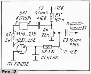
The essence of this non-standard solutions is that the variable resistor complemented by the field-effect transistor included in the control circuit of the attenuator integrated amplifier CAR according to the scheme shown in Fig. 2. Most often pin 5 of the chip is connected to GND via a resistor 10 com, which is removed. Since the pin 5 is specially designed for electronic gain control, it would be possible to build a fully electronic controller, but this solution is not always satisfactory. And, above all, here's why: when, for example, in the TV if amplifier sound closed electronically at its output is still present significant the background level and noise.
In the present embodiment of the variable resistor remains, which significantly reduces the signal together with the above-mentioned noises before going into effect "electronics". In other words, the correction curve adjustment variable resistor occurs mainly in the lower (scheme) part, i.e. small the loudness of the sound. In addition, easily done mate volume control with switch.
It should also be noted that the use of electronic control and assumes a significant change in the installation, as in the present embodiment this is not required.
The originality of the solution lies in combining these two adjustments at the same time - traditional resistive and electronic with engine the same variable resistor. When the engine is in upper circuit positions, "electronics" off, as the gate field-effect transistor VT1 through a divider R3R4 comes with a closing voltage.
As you move the engine down (the scheme), when the signal level is taken from it will be reduced by approximately three times (depending on the selection of elements), field-effect transistor starts to open and reduce the signal already output the chips through the built-in attenuator. The result is greatly reduced the visibility of noise in traditional adjusting circuit and provides the necessary smooth adjustment.
The selection of resistors R1 and R3 can be achieved in a timely and smooth adjustment the volume at the desired location of the turn knob. Such a selection will need in any case, because of the variation of the input specifications of the applied field of the transistor.
The proposed site adjustment is applied in a portable TV electronics 404", having mated with volume control power switch from external battery. For reference, when creating a node in the diagram (Fig. 2) shows the limits of change of voltage at pin 5 of the chip from the open state attenuator (+2.1) to complete its operation (+1,45 In). Voltage, mentioned in the other points, can be different, depending on the settings the used transistor.
Note that when using the described node problem occurs with the inclusion of oxide capacitors before and after the volume control. During normal turn on they were connected with the common wire through a variable resistor. The proposed the version with him on the capacitors is supplied a positive voltage. Therefore, you must make sure to not change the polarity of the voltage on capacitors. Otherwise you'll have to change the polarity of their inclusion.
Installation of this relatively simple knot can be done on a small circuit Board with two of the conclusions that solder it instead of the remote resistor connecting conclusion 5 chips with the common wire. The conductor that connects the slider to the resistor the volume of the R4 resistor R2 can not be escaped, since the RF pulse and interference filter eliminates R2C1.
In node you can use almost any variable resistor of suitable size and rating. If the device on the regulator required switch, variable resistor modify: remove the cover screen, existing engine, replace the engine from the old regulator and close the lid from him, which strengthened the switch. Then choose the resistors R1 and R3 so that a full loss of signal at the output of node come before operation switch (see curve In Fig. 1).
Author: S. Tuzhilin, Schelkovo, Moscow region.