


")

In many families there are photographic film and slides, small photos. For make it easy and convenient to collectively view, the author of the article suggests use a simple television slide projector. It is applicable in a number of other cases.
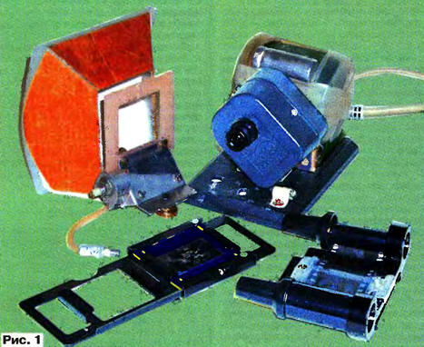
Many hams remain negative black and white and color photographic film, and the photos are missing, or positive photographic film and slides. Sometimes you want them to view alone or with family. However, it is often a good slide projector no. When his presence is required darkening of the room for viewing. To solve these problems, a simple television slide projector, appearance which is shown in action on the 1st S. cover, and in a disassembled form in Fig. 1 in the text. It is only necessary to connect it to black and white or color TV, available in almost every family. To connect the projector apparatus must be equipped with low-frequency input "Video" for submitting the video.
In addition to these applications, the projector can be used for collective view enlarged photos in the album, figures, other objects, in particular printed circuit boards, with the necessary lighting, as well as images in the microscope, spotting scope, telescope, etc.
Block diagram of teledeporte presented in Fig. 2.
The projector consists of backlight devices camera roll or slide fixture (frame) for them host, a miniature television camera, the inverter signal and the block power. The illuminated image on the film or slide to be projected in the camera lens, the output of which is obtained a video signal. If the camera roll or slide positive, the signal is fed directly to the video input TV. When negative images of the video signal from the video camera is necessary invert preserving the polarity of sync pulses. To do this, and is a special inverter video signal included in the circuit in such needed.
Schematic diagram of teledeporte depicted in Fig. 3. The apparatus is equipped with miniature open frame video camera SAMSUNG - AV202 commonly used in intruder alarm systems, with a lens having an angle of 90°. It provides a video signal with amplitude 1 V and a black and white image with resolution of 380 TV lines.
In the device podwiki the projector is equipped with five LEDs HL1 - HL5, brightness glow which you can change the variable resistor R2, which regulates the current through them. If you are viewing the positive image output camera video signal passes through the switch SA1 set in the position "Nein.", the output of the projector and input "Video" connected to coaxial cable TV.
(click to enlarge)
When viewing negative images, the switch SA1 is placed at the position "Inv.". In this case, the video signal from the camera is fed via the capacitor C2 for the inverter, collected on transistors VT1-VT3. Chain R3C1D2 sets the operating point inverter. The capacitor C2 and the diode VD1 provide a binding negative peaks clock signal on the base of the transistor VT1 voltage level in the operating point.
Transistor VT1 is assembled cascade with a split load. Moreover, the mode of operation transistor VT1 is selected such that the resistor R6 is allocated only negative non-inverted sync pulses of the video signal. On the collector of transistor VT1 is obtained by an inverted video signal with positive sync pulse, which through the resistor R5 to the input emitter follower transistor VT3. However, as a result of exposure negative pulses from the resistor R6 to the emitter of the transistor VT2, connected to the input of the emitter follower, which is replaced by a positive clock negative.
At the output of the emitter follower is formed actually inverted the non-inverted video signal with the synchronizing pulses, which appear on the output projector. A trimming resistor R8 sets the voltage on the base transistor VT2, at which the required proportional addition inverted non-inverted video signal and synchronization signals.
Power supply (adapter) the projector needs to ensure stable voltage of 12 V at a current of 200 mA.
The projector can be used any resistors and capacitors. Connector XW1 - type "Tulip". The switch SA1 - slide. Transistors can be used any of the series KT3102, CT appropriate structure.
Design teledeporte shown in Fig. 4. Open-frame camera and the fee inverter are combined in a common housing (switch SA1 is installed on it), situated on turning (around the lens axis by ±90°) bracket. Bracket and power supply (I used homemade, but you can apply ready) mounted on a common base.
Illumination unit consisting of a reflector, a light-proof screen LEDs HL1 - HL5, the adjusting resistor R2 and a constant resistor R1, together with the fixture (holder) to install the framework with film or the slide (e.g. slide projector "Light" or improvised) is made removable. It provides (if removed) the pictures in the album and other images. The distance between the holder and the lens (about 20 mm) is not critical, since the focus can be changed.
To view a color image with color positive film, and slides you need to apply a color camera with white light illumination and color TV.
Author: L. Kononenko, Moscow