We will remind, why would the TV need a device PIP "picture in picture" (or POP "Frame off screen). It allows the TV with the main nurago the image to get one or several small frames other programs, located either in the main field (PIP) or near it (POP). About some chips for such devices it has already been told the HB stranicu "Radio". However, since then appeared chip new generations. They considered in the published article here. The author also describes a schematic diagram of one of variants of the device, given its circuit Board.
SIEMENS has developed several generations of chips for devices "in the Frame the frame". Kit features the first generation (SDA9086 - SDA9088) were considered in [1 and 2]. In 1993 we had a set of chips of the second generation: SDA9187 and SDA9188. The first one contains three ADC and circuit forming a digital signals, and the second is a processor with PIP field and lowercase memories.
The use of the device in "picture in picture" of the third chip (SDA9086), forming the clock signal of the main image, not necessarily. In this case the clock signal may be generated by internal PLL device within the composition processor SDA9188. It connects quartz resonator frequency 20,48 MHz.
Instead of quartz, you can apply a ceramic resonator. Choice of internal the PLL device is provided via the l2C bus. For this bit in register d2 SDA9188 with the sub address 04 write level 0. The address of the chip is the same as that of the SDA9088, i.e. 00101110.
In the second generation chip ADC resolution is increased from five to six that improved the quality of the frame is inserted into the main image. There are two its size is 1/9 and 1/16 of the area of the screen. The chip can work in TVs with a refresh rate of 50 and 100 Hz (bit d3 in register 00 is set equal to 0 or 1 respectively).
The analog luminance and color difference signals with positive or negative the polarity of the three ADC in the chip SDA9187 working with a clock frequency of 13.5 MHz (100 Hz clock frequency is increased to 27 MHz) is converted into three six bit digital signal. When positive polarity is applied to chip chroma signals pin 14 should be connected to a common wire. The free state of this output or feed it voltage +5 V corresponds to the negative polarity of the chroma signals.
The nominal scale of input signals Y, U, V is equal to 1 V. Exemplary permanent stress work for them in the chip SDA9187 on the divider, consisting of internal resistors connected between pins 18, 20, 22 and 24. To to reduce the solution amplitude to 0.5 ADC, between pins 20 and 22 include external resistor 128 Ohms. Nominal input swings signals increase to 2 if between pins 18 and 20 to connect the resistor resistance 530 Ohms between pins 22 and 24 by a resistor 343 Ohm.
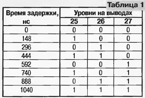
Color difference signals are multiplexed. The result is desethylatrazine the thread in which the luminance signal occupies six bits. For precise alignment of the luminance signal and the chromaticity provided adjustable the delay of the luminance signal. Adjustment is provided by changing external voltages of the pins 25 and 27 in accordance with table. 1.

The reduction in the number of lines and samples per line in the small image occurs in interpolation of horizontal and vertical filters, which prevents the interference distortion. Then the information is recorded in the memory volume 169812 bits (212 counts in the string, 89 string, 9 bits).
Read the small image will feature in one of the four corners of the main. The output area selected for l2C bus (bits d6 and d7 in register 03). Also on the bus l2C is possible to displace the input image vertically and horizontally (bits d0 - d3 register 02 and d0 - d5 of the register 03). Image playback is possible in field or frame mode. When installing field mode (bit d7 in register with address 06 contains level 0) in memory is written to only one field. In frame mode (d7 = 1) memory constantly operates in the recording mode.
Chip PIP device used in the standards D/K and B/G (625 lines) and the American standard M (525 lines).
The small image can be provided with a frame (bit d0 of register 01 contains level 1). The thickness of its lines and color are set via the I2C bus (bits d4, d5 in register 05 and d1 - d3 in register 01). When 1/9 size small picture consists of 88 lines, each of which contains 212 samples the luminance signal and the 53 count citratest-tion signals. When size 1/16 it contains 66 lines and 160 samples the luminance signal in the line.
The size of the image vertically and horizontally installed separately (bits d6 and d7 register 05). Hence the ability to play small image format 16:9 screen with 4:3 format. It is enough apply mode output with the number of rows 66 and the number of counts in the line 212. Similarly, applying the mode 88 rows and 160 samples per line, replicate picture format 4:3 screen with 16:9 format. The outputs of the processor SDA9188 can output in the format R, G, b or Y, U, V (level 1 or 0 in the bit d1 register 00). Perhaps getting fixed, so-called "frozen" image. To do this, bit d5 in register 00 is set equal to the level 1.
Device PIP second generation can be used in small channel image chroma decoder without delay on the line. The first such a solution proposed in [3]. The possibility of eliminating the delay caused interpolation of lines in the vertical filter unit PIP. At the output of the decoder in the PAL mode during each of the rows are highlighted both chroma signal with half amplitude (relative to nominal). After the vertical filter the amplitude of the signal increase to the nominal level. In SECAM mode on the outputs of the decoder through the line highlighted signals R - Y and B - Y with nominal (unit) amplitude. After averaging in the vertical filter signals with half the amplitude. So that was the same the color saturation of the small image in the modes of PAL and SECAM, it is necessary to increase the scope SECAM chroma signals twice.
The chroma decoder must produce the identification signal is a color standard, which arrives at the Central processor. In SECAM mode last writes in bit d7 of register with subaddress 07 level 1, then the transmission coefficient for chroma signals is doubled.
Chip PIP second generation is produced in the enclosure designed for surface mount P - DSO - 28, which has 28 pins.
In 1995 there was a chip PIP third generation SDA9288 in which combines the functions of the circuits SDA9187 and SDA9188. This chip, as set the second generation, is providing one additional image with area of 1/9 or 1/16 from the base image. However, there are new opportunities. First of all, you can get the image format POP ("Frame outside frame").
The chip contains a switchable matrix of R, G, B (for standard SECAM/PAL NTSC - US and NTSC - Japan). A possible choice for the I2C bus to one of 4096 colors frame. Adjusting the delay time of the luminance signal is provided not change external voltage and I2C bus (bits d0-d2 in register 04).
In the chip by changing the external voltage at pin 15 can be installed one of three possible locations (11010110 if U15 = 0; 11011100 if U15 = 2.5 V and 11011110 if U15 = 5 V). This allows using three PIP processor, display on the screen three independent image.
Information about the SECAM signal reception may be filed directly at the output 26. In this case, the gain of the chroma signals is doubled.
Chip SDA9288 made in the case of P - DSO - 32 - 2 having 32 output.
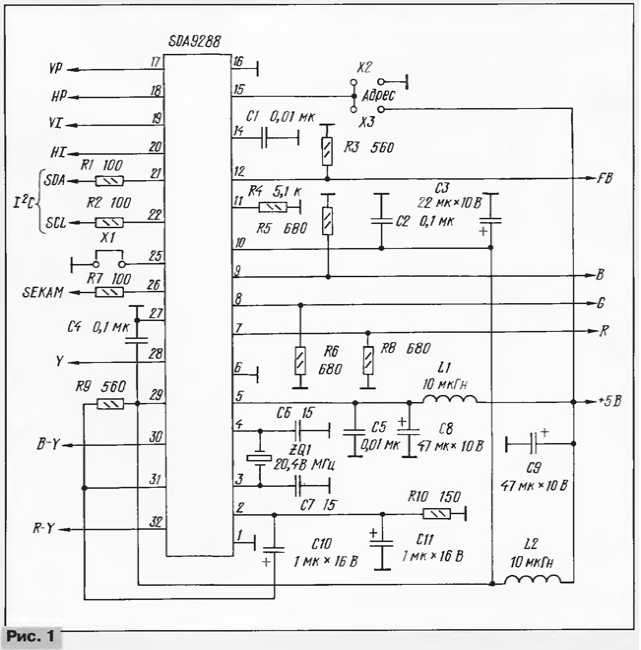
Fig. 1 illustrates the inclusion of a chip SDA9288. Letters VP and designated HP human and flyback pulses of the main image, respectively, and letters VI and HI - similar pulses input image; FB - blanking weekend pulses. Jumper x2 and XS are used for selection of the chip address.

Chip SDA9189, released in 1995, called "Quad - PIP". This the name is given because it can create the input frame with an area equal to 1/4 the area of the main image. In addition, the chip provides 17 more options for removing small images, including four size 1/16, three size 1/9, nine size 1/32. Four options are designed for the format 16:9. For example, one of them - the three images to the right or to the left standard 4:3.
Processor SDA9189 used together with chip SDA9187 performing as in the PIP devices of the second generation, features triple ADC and driver the flow of digital information.
The main purpose of "Quad - PIP" scan the selected channels. One the image is moving, the rest frozen. Perhaps the introduction in each image information labels of five characters (Latin letters, digits or symbols that satisfy the ASCII codes). Provided definition of parity playing field, which contributes to normal operation in frame mode.
The chip is not used, the entire active portion of the input image. When sampling covered 576 samples of the luminance signal in each line 252 line in field. As in the chips of the second generation, for sealing of information are horizontal and vertical interpolation filters. For size 1/4 in filters averaged only two reference and two rows, for 1/9 - three count and line, and 1/36 for six counts and row. The information obtained is recorded in the memory, which has a volume of 329184 bit. If you are playing single image frame rate is 50 Hz and the core standards and input images are the same (for example, 625 lines), can be realized frame mode when written as the even and odd fields. In this case with clarity and temporal resolution. In all other cases recorded only odd or even fields.
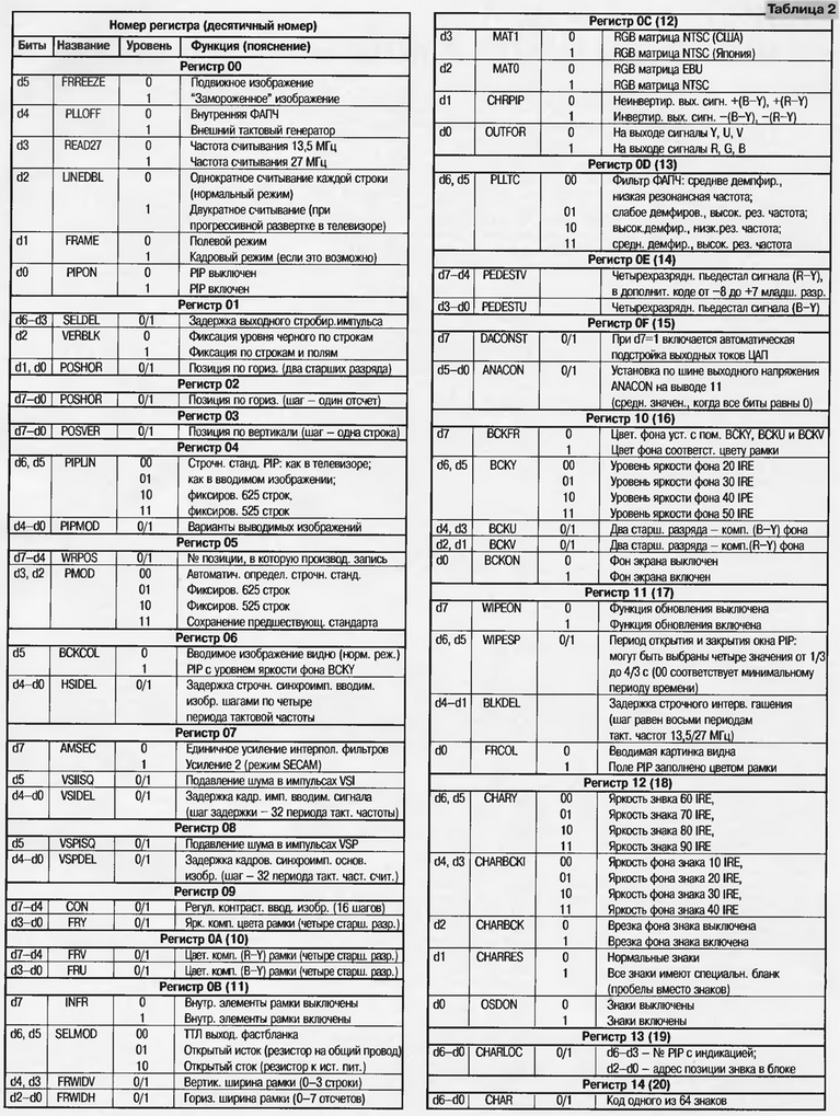
When reading the small image from the memory position it on the TV set vertically and horizontally via the l2C bus. For write commands, the processor has 21 eight-bit register. The content of registers is explained in table. 2. Chip SDA9189 supplied with three same addresses as SDA9288. The degree shift the image horizontally and vertically recorded in the registers 02 and 03.

Small picture if you wish, edging frame. Its color set bits d0-d3 in register 09 (signal level Y), d0-d3 and d4-d7 in register 10 (signal levels U and V). There are a total of 4096 colors. When playing multiple images between them injected internal frame. If bit d0 in register 16 is equal to 1, on the TV screen, in addition to the input image, the background appears with software-defined color.
The chip outputs can be output signals R, G, B (bit d0 of the register 12 equal to 1), or Y, U, V (this bit is equal to 0). The value of the bit d1 in the same register determines the polarity of the output chroma signals (they will be non-inverted when d1 = 0).
Processor SDA9189 as SDA9188, allows you to choose one of the three matrices R, G, In: European (PAL and SECAM - standard EBU), the Asian (for Japanese version of NTSC) and American. The EBU matrix is selected, when the bit d2 of the register 11 is $ 0. Differences are due to different color coordinates of white and primary colors in the picture tubes used in these countries. For different matrices will turn out different amplitudes and chroma signals the phase angles relative to the axis B - Y. They are listed in table. 3.

The switch R, G, B, in the video processor, processor PIP blanking output signal. His delay in relation to the luminance signal and color difference signals (bits d3 - d6 of the register 01) set on the l2C bus. This ensures the exact position of the input of the image relative to the frame. Output signals removed with external resistors loads, through which currents flow in the three DACS.
Author: B. Khokhlov, Moscow


