


")

The sound quality of television programs in many domestic and foreign TVs, unfortunately, remains quite low, especially if the transfer is accompanied by subtitles. Quasi-parallel channel a radical way to ensure a clean high-quality sound. There is also the problem of getting sound in TV, host transmission only in standard B/G. this will be discussed in a published article.
In Russia and other CIS countries in various ways continues to flow overseas video equipment (TVs, VCRs, etc.). which is designed to accommodate television signals exclusively PAL. In our country such devices don't create problems getting image, since almost all foreign TVs are decoders which convert the video signals we adopted the TV system SECAM video signals in the PAL system (or the other) [1.2]. It should be borne in mind that in the countries of Western Europe FC image equal to 38.9. instead of 38 MHz, as in our standard [3]. And it can lead to the need to adjust the output of filter channel selector though such cases are quite rare.
They are much more complicated in foreign TVs with sound accompaniment, in which no multisig systematic block sound Because we know that in currently, depending on the spacing of carrier image and sound escorts in different RF standards second if sound can be equal to 4.5; 5.5; 6 and 6.5 MHz Typically, these TVs are one of them 14]. So, for standards B, G, N is equal to 5.5 MHz, Therefore, to sound escorts when your TV reception standards D/K, in which the second inverter is equal to 6.5 MHz, it is necessary to convert this second if frequency 5.5 MHz.
However, the conversion is not only can provide a good sound support, as the first if of sound (31,5 MHz our standard and 32.5 MHz standards, G. N.) is located on the extended shelf frequency response of UPCI. what allows the passage of both the inverter. Having problems with all vehicles, which provides for joint processing of the video signal and sound signal on the first inverter. And these TVs, both foreign and domestic, rather a lot of them In the signal of the second inverter excels at detecting full color TV's video signal (PZT) as a result of the beating of the first inverter. It is inevitable leads to the mutual influence of the brightness-Noi. color and sound components, consequently, to the emergence of significant distortion. The second signal is supplied to the inverter entrance UPCS distorted, making it difficult to its limiter. As a result, in dedicated 3H signal interference is taking place, manifested particularly noticeable when the transfer of credits on the image. Eliminate them and get a good sound maintenance replacing the filter in the channel UPCS or the conversion of the second inverter impossible.
To solve this problem in apparatus designed to receive television signals standards B, G, N, and improve the sound in them (this applies to domestic TV), radio Amateurs have resorted to various ways. One one is the use of so-called quasi-parallel channel. It seems the most effective technical solution, as it provides separate detection of video and audio signals that can successfully suppress audio channel the unwanted videomastasia and reduce the noise level by about 10 dB [5].
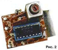
Analysis of building and practical repetition of blocks of quasi-parallel channel for example, considered in [6]. and second converters FC shows that they difficult to manufacture and configure. Therefore, to eliminate these shortcomings hams offers a relatively simple quasi-parallel option channel - block "clean" sound. Its schematic diagram is depicted in Fig. 1. and the appearance shown in Fig. 2.
The main purpose of the block - amplification and conversion of the audio signal maintenance standards V. G. N in the signal of the second inverter standards D, K, L, K1 in mode first if full level after the channel selector) implementation dual APCS, discussed below, improving not only the sound quality, but also the parameters of the radio channel. This unit may be applied in foreign TVs, VCRs and domestic vehicles production. In TV it provides the improvement of the basic technical characteristics of sound channel: a significant increase in sensitivity and class complete elimination of noise in the soundtrack of TV programs (including subtitles), improve the sound quality in any standards at weak the signals in the antenna, and it hardly depends on their level, as in the block provided ARU about 60 dB. The disadvantage of the block include the need adjustment of demodulator circuit UPCS apparatus in which it is mounted.
The unit was designed for use in TV LEONARDO-1512 PHILIPS a channel selector which has a symmetrical output. However, it can be connected to the selector with an unbalanced output. In this case, the input signal IF2 (see Fig. 1) must be connected to GND.
From the output of the channel selector, the frequencies of image and sound arrive at the balanced input (pins 1 and 16) of a chip of DA1. The received signal second if of sound 6.5 MHz through piezoelectric band-pass filter Z1 on surfactants runs on UPCS TV. Filter Z1 suppresses first if of sound 32.5 MHz. Capacitor C4 filters the AGC voltage.
Voltage indicated on the diagram, measured by consumption of the unit current of 18 mA. The variation of current in a circuit can be in the range from 17 to 27 mA, which due to the tolerances on the elements of the chip.
The unit is well aligned with the output of the channel selector and to the input of UPCS. no bypasses the output of the selector and has no effect on the image. It provides also the ability to save (if necessary) native standard in the apparatus when you improve the sound quality.
In the applicable unit capacitors K10-47. K10-49 and ceramic. Resistors - MLT. The inductor L2 - PDM-0.1. Filter SFE (Z1) can be replaced by the OP1 filter P8-62.02.
The coil L1 is wound a coil to a coil on a plastic frame, having podstroechnik carbonyl iron. The outer diameter of the cage -3…5 mm, height - not more than 15 mm. the Coil has five turns of PEV-1 0.25.
All elements of the unit are mounted on a circuit Board from unilateral polygermanes fiberglass, a drawing of which is shown in Fig. 3.
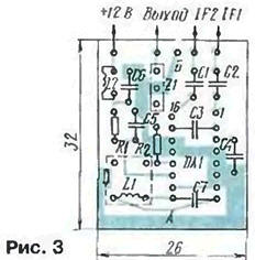
The Resistors R1. R2 and the inductor L2 is set perpendicular to the PCB and the capacitors C3 and C7 solder side of the printed conductors.
When installed in a particular model, if the TV before UPCS strip included the filter on the desired second inverter, and before him - the input circuit of RC elements unit can be simplified by eliminating the filter Z1 and resistor R2 (their point of connection connect jumpers). The unit output is connected to the input circuit of the filter apparatus, pre-breaking walking toward her guide. If the filter apparatus designed for another second if. it must be replaced.
Inside the block is attached by a metal strip size 10x25 mm. which first soldered to the side And the PCB, and then with the block to the screen of the TV tuner in a convenient location and in any position. For connections unit in the apparatus used wire MGTF (shielded wire is not used). Inputs signals IF1 and IF2 connected to the outputs of the channel selector without breaking the existing installation. If the selector has a single-ended output, then the input signal IF2 is connected to the point B on the Board (with common wire). The voltage of +12 V on the block it is recommended to remove before decoupling resistors in circuits of this power supply
To configure the unit, first install podstroechnik coil L1 in average position. Then turn the TV on first gear and rotation counterclockwise of podstroechnik loop demodulator staff get UPCS the highest volume and best quality (without interference and noise) sound support. Then just adjust and contour L1C7 block. This configuration both contours are repeated two or three times. The result of fine tuning needs to be practically complete suppression of the signal at the output of the unit and clean the soundtrack is taken by the television, and finally, check it on all other working channels. If necessary, the adjustment of the precise contours of to obtain noiseless sound.
To ensure foreign video devices dual-band the sound or replace if necessary defective UPCS chips (TV LEONARDO-1512 this is TDA8190. and provided that other devices operate [2]). was developed by pretty simple dual-band UPCS. schematic diagram of which is shown in Fig. 4.
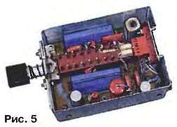
Consumed by the unit, the current is 27 mA. The appearance of such UPCS shown in Fig. 5.
It can be used in vehicles, both foreign and domestic production. Its drawback is the necessity of using the switch for manual transition from one sound standard to another.
The signal of the second inverter from the output of the above-described block sound is input to UPCS. In depending on the value of the second inverter (5.5 or 6.5 MHz) switch SB1 include the micro-DA2 (5.5 MHz) or DA3 (6.5 MHz). It should be borne in mind that when joint work block sound with two standard UPCS filter Z1 in block sound it is necessary to replace the bridge because in UPCS have their filters 72 and Z3. The micro UPCS operate according to the scheme: limit of detection - gain. Resistor R3 provides the required level of the output signal, and the capacitor C3 stabilizes the value of the DC voltage at pin 8 assemblies and filters out noise. With the release UPCS signal fed to the amplifier power 3H. where to adjust the volume.
The unit makes use of resistors MLT and all-ceramic and oxide capacitors.
All the details UPCS mounted on a printed circuit Board, a drawing of which is shown in Fig. 6.
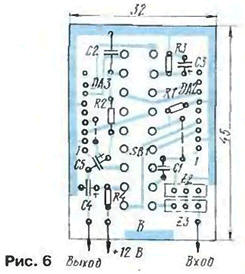
The unit is applicable switch P2K or SDH-61. The switch with the card attached to dural corner-bracket, which is screwed into a selected convenient the location of the device. The resistors on the Board set perpendicular to it.
The unit is placed in a metal screen with a height of 28 mm. the Screen is soldered to a common wire Board block on three sides and to the ground V. Screen capped from above and from the bottom. The unit is connected to the apparatus via the connector RGN-1-1 (see Fig. 5).
Literature
Author: E. Hajdel, Smolensk