In operation the TVs OPENCT equipped with blocks SVP-4, capable of receiving on six channels. Currently this is not enough. Upgrading TVs OPENCT by replacing the SVP-4 blocks of fifth generation TVs providing reception for 55 channels is an expensive and complicated procedure.
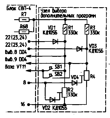
Offers significantly cheaper and more simple to modify existing blocks SVP-4, which allows to receive an additional two channels. The essence of the revision is as follows. In scheme, the device selection unit SVP-4 [1] applied the option to include a binary-decimal decoder CID [2], which involves only inputs A0, A1, and A2, respectively, the outputs Y0...Y6. You can still receive eight channels, but the on-Board outputs Y2, Y3 and Y6 (pins 8,9 and 10 respectively) combined than the number of channels is reduced to six. Therefore, if you remove the jumpers connecting together the findings 8, 9 and 10 of the decoder, and connected to pin 8 and node 9, a schematic diagram of which is shown in the figure, it becomes possible to receive the two additional channels.

Node select additional programs consists of two identical channels. Here is one of them. The resistor R1 to destination similar to the resistors R8 R13...device selection unit SVP-4, and diodes VD1, VD2 and variable resistor R2 is a single channel device presetting unit SVP-4 (for example VD14 and R61 in [1], respectively). In order to simplify and reduce the cost of improvements with a slight decrease ease of reference, the node selecting additional programs does not have the function of indication of the selected program. These same considerations are excluded and the function of switching ranges, in which the unit SVP-4 is performed by the switches B1...B6 device presets. Offers a fixed connection of the cathodes of the diodes VD1 and VD3 to the Board presetting unit SVP-4 - to-point 22 (II band), point 23 (IV range) or to a point 24 (III band). If additional television channels belong to the I range, the circuits of the diodes VD1 and VD3 from the scheme can be deleted.
To perform the proposed improvements should:
- on-Board device selection unit SVP-4, remove the jumpers connecting together the findings 8, 9 and 10 of the decoder DD4 KID;
- assemble the unit select additional programs and connect it according to the schematic diagram shown in the figure.
How to configure additional channels similar to the one defined in [3]:
switch HRA-PIF [3] to position PIF;
- press the button of the switch SB1 site selection of additional programs;
- to make a gradual adjustment to the first additional channel with a variable resistor R2 of node selecting additional programs;
- press the button of the switch SB2 site selection of additional programs;
- to produce a smooth tuning to a second channel using a variable resistor R4 site selection of additional programs;
switch HRA-PIF to position the AFC.
After that, to include an additional channel, just press the appropriate button - SB1 or SB2.
In the node applied resistors MLT-0,125 W (R1, R3) and SDR-36 (R2, R4), diodes CD with any letter index or D (VD4 VD1...). The switches SB1, SB2 - any small, such as APF-15.
Literature:
1. Elyashkevich S., Chisinau S. Units and modules are unified color TVs. A reference guide. - M.: Radio and communication, 1982.
2. Bogdanovich M., Grell I. Prokhorenko V., V. Shalima Digital integrated circuits. Ref. -Mn.: Belarus, 1991.
3. TV "birch TS-208" (OPENCT-M-61-s-1). Manual. - Kharkov, 1986.
Author: V. Babenko, Kharkov; Publication: N. Bolshakov, rf.atnn.ru


