


")

When repairing TVs of radiomekhaniki and ham radio operators are often faced with problems replacement elements (not in the sale) and blocks (for the purpose improve the reliability of the apparatus). Author of published collections here materials shares his experience of overcoming these difficulties by applying the equivalent chip K416KH1 and replacing the power source of BPI-411 on more reliable MP-3-3.
Analogue chips CKN
In the repair of radio equipment have had to face the exit building chips CCN applied in feather-touch selection box television programs (BWTP) TVs "Elek-Tronic-C", "Electronics-C", which are spread quite widely. To buy it almost impossible, as its no longer produced. To restore the performance of these televisions that had to develop the option of replacing this the chip, which is offered repairers and hams.
Chip CCN is a switch with two sets of electronic keys that are controlled by triggers. When you press the button BVTP one of the programs triggers corresponding to the trigger button, managing two keys. One of them applies a voltage +27 V for the resistor settings for the selected program, and second, opening, includes an appropriate site selection sub-band settings and indicator programs.
When designing analog equivalent circuits was tasked with obtaining relatively simple devices with minimal changes in the TV. Collected the equivalent of the chip was verified in TV and established. Any differences or failures of devices such replacements do not was observed.
Schematic diagram of the analog shown in Fig. 1. Its main feature - use instead of keys, a switching voltage +27 V, Comparators at the shelter. The fact is that the majority of the available circuits, including the keys on of field or bipolar transistors, are not capable of switching the voltage and the use of individual transistors would lead to a significant increase size equivalent. The use of Comparators required just two circuits DA1, DA2 and two resistors.
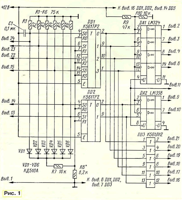
The Comparators control the triggers on chips DD1, DD2, which is assembled dependent quasi-touch switch. During short-term feeding (via click on any of the inputs of switch voltage of +12 V on its corresponding the output level is set to high and all other outputs low. These levels do to the non-inverting input of the comparator and the inverting inputs voltage is within +2…with 4 In divider R9R10. As a result, when a low level at the inputs of Comparators at their outputs sets the voltage close to zero, and at high level at the input to the corresponding output there is a voltage +26.5 In needed to configure the TV.
Elements of the chip DD3 control circuits selection of sub-bands and led indicators, reversing the signals coming from the outputs of the switch. Capacitor C1 provides the installation of the first trigger switch is in one state when you turn on the TV power, i.e., the introduction of the first program (which is set to the 1 button).
Unlike chips CKN on analogue must separately apply a voltage power +12 V available in BWTP. In addition, the switch button programs in the TV one contact connected to the terminals (ISIS, 22-24) chip CCN and second contacts are connected together and a common wire. Last must be disconnected from the common wire, cutting the one printed conductor on Board BWTP, and submit them via the jumper, the voltage of +12 V. This is due to what triggers the equivalent of a controlled positive voltage, and triggers chip - connection of the inputs with the common wire. This is different connect the equivalent of chip. It should also on the Board BVTP desoldering a conclusion diode connected to the output 24 of the chip.
The printed circuit Board is made of bilateral foil fiberglass and is shown in Fig. 2. Its small size allows to place equivalent inside BVTP in place vypayannoy faulty chip.
On the Board (Fig. 2,b) the resistors and capacitor for surface mounting size 1206 on the side opposite the location of the other parts (Fig. 2,a). On the same side represents the locations on the printed conductors to which solder the wires that serve as the findings of the analogue. Them to be marked. The use of plenary items reduced the Board size.
IC LM324 (DA1) can be replaced by COD, CUD, a LM358 (DA2) - SA, CRUD. Chip series C interchangeable with similar ones from the series CR. Instead of diodes series CD you can use the diodes of the series KD521, KD522 or similar. All the diodes are soldered perpendicular to the Board surface also reduce its size.
The collected analog wires-solder conclusions in BVTP the TV remote instead chip in accordance with his scheme.
Correctly assembled and connected equivalent in the establishment does not need. In the case of fuzzy switching apps when you press the button, you can pick up resistor R8. However, when specified in the scheme face value of the collected specimens the device worked reliably.
Replacement of BPI-411 on MP-3-3
The repair of domestic TV sets, ham radio operators are often faced with failures power sources BIP-411 in TVs, especially the type of "horizon", for example "Orizon-CD". One of the very common problems can be called multiple protection activity in the block. He workable, but when you turn on the TV often starts with only a few attempts. All elements in the block is serviceable, replacement of capacitors also gives nothing. Slightly improves the performance of source capacity expansion (up to 200 µf) capacitor C3 connected between the findings of the collector and emitter transistor VT2. However, it does not eliminate the problem.
To get rid of such problems, it is best to replace the WPO-411 and more reliable a stable power source MP-3-3 (or equivalent) applied in the third generation TVs. It has all the voltage necessary for the work of these TVs, in addition to voltage 6.3 In feeding the glow of the tube, as the third generation TVs voltage for the glow of the tube is removed from the horizontal sweep transformer.
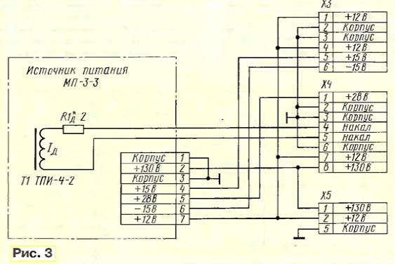
Replacement is required to make a simple adapter, which is depicted in Fig. 3, as the connectors in these power supplies do not meet each other. The filament voltage of the tube serves to pins 4 and 5 of connector X4 adapter. The voltage can be obtained in different ways. It is best to add in TV separate transformer with a voltage in the secondary winding of 6.3 V. It must provide current in the range of 0.6. ..0,8 A. Space to accommodate the transformer in the TV abound.
The second method is connecting the glow of the tube through resistor 2-3 Ohms and a capacity of not less than 4 watts to the winding 7-8 flyback transformer, as made in the third generation TVs. Winding of the transformer in a string these TVs are not involved.
Finally, the third method illustrated Fig. 3. He is to add another one winding in the transformer TPI-4-2 in the power supply MP-3-3. For this raspalaut screen covering the transformer, and is wound on top of existing winding six or seven turns of wire of diameter 0,5…0,7 mm. Very convenient to use for this purpose a mounting wire, for example, MGTF. To check voltage in the secondary winding includes a power source MP-3-3 in the network, pre-load chain +130 V filament lamp (220V, 100W) and soldered to the additional coil resistor PEV-7 resistance of 10-15 Ohms. Instead resistor can also use the lamp filament voltage of 6.3 V and power 4…5 watts. Measure the voltage across the resistor (or light) to the multimeter in the measurement mode AC voltage. Optionally, if the value voltage does not correspond to 6.3 V, add or reduce the number of turns in coil. Precisely this tension can be achieved by selection of additional resistor Ad. After receiving the required voltage, establish into place the screen transformer.
Charge power source MP-3 to-3 to replace the need to choose with small the line filter capacitors. If it has capacitors K50-31, screwed nuts, they need to replace the C50-35 or imported. Can use one capacitor 150-200 UF voltage is not less than 350 V. New Board floats in place of the old.
Mounted in this way, the power source in the specified TV securely has been operating for several years. It should also be noted that the value of the source power MP-3-3 is almost two times lower than the cost of BPI-411.
Author: I. Korotkov, p. Bucha, Kiev region, Ukraine