


")

To improve the sound in domestic and imported TVs, you can add them in the mode "Pseudostereo". Under what conditions and how this can be done, is told in the published article here.
A large number of TVs available on the market and use of the consumers are mostly mono sound. And many users would like to have a stereo or at least pseudo stereophonic support, significantly improving sound perception. But if the TV has only one dynamic head, without using speakers change anything. However, if the TV contains two built-in head on the sides of the housing, and a power amplifier has 3H two separate channels, then adding a simple device you can enter in TV mode "Pseudostereo". This regime can be supplemented and stereo a model in which it is absent.
Most just for this purpose to use chip TDA3810 PHILIPS. This is a surround sound processor, detailed description of which was given in [1]. The magazine described the use of this chip in TVs ZUSTST [2]. Here is offered the option to install a CPU in a modern imported LG TV - 21S10E (chassis MC-84A) South Korean production.
This model provides mono sound, but on the sides its housing has two wideband drivers with maximum with a capacity of 15 watts each. In addition, the TV used a two-channel the power amplifier on a chip LA4282 (symbol on the circuit Board - IC601). The input to each channel of the 3H signal is fed via resistors connected together R604 (left channel) and R601 (right channel). Before this mono 3H passes through the chip KIA4558P (IC603). It shapes up the bass boost in signal when operating in the mode of UBB (ULTRA BASS BOOSTER). Command the on mode with the remote control by pressing the "UBB". At the same time on the TV screen is displayed for three seconds, the character in the form of two intersecting rings with the triangles on the sides. In this mode, the output transistor base Q680 you receive a constant voltage of +4.8 V. If the specified mode is turned off the voltage is close to zero.
All of the above is necessary in order to more clearly imagine what signals can be used in refining and where to connect described below the structure.
Schematic diagram of proposed improvements on pseudotropicalis chip TDA3810 depicted in Fig. 1. And applied the model with the inclusion of minor changes. Her conclusions 7 and 8 for indicator LEDs left free. One of the conclusions of management (12) is connected to the common wire, since the mode of "Extended stereo" device is not used. The second conclusion management (11) through the diode VD1 is connected to the output of the base mentioned above transistor Q680.
In addition, the motherboard of the TV unsolder the terminal of the resistor R604 and R601, which receives the signal from the chip KIA4558P (IC603). At any (of released from the terminal of the resistor) hole solder a wire coming from bonded together by capacitors C1 and C4 of the device. And to webanim conclusions resistors R604 R601 and connect the output of the left and right channels of the chip respectively, through capacitors C10 and C15). Pin 10 of the chip DA1 connected to a common wire of the TV. Supply voltage +12 V on the chip DA1 (pin 18) is easiest to apply with the pin 8 of the IC IC603 TV.
Now, when the TV is in normal mode ("UBB" off) DA1 chip pseudostereo-Converter operates in Stereo mode (on pin 11 - 0). But since the TV signal is monaural, the sound speakers will be monaural. If the TV to turn on the "UBB", together with the rise of the low frequency signal 34 IC IC603 TV will appear and Pseudostereo", as the pin 11 of the chip will be disconnected from TDA3810 the common wire (the cathode of the diode VD1 received voltage +4.8 V). Mentioned above the symbol that appeared on the TV screen, will indicate the simultaneous operation of modes "UBB" and "Pseudostereo". Therefore, no additional indicator is not required.
Collected device on a printed circuit Board, the drawing and arrangement of parts it is presented in Fig. 2. Resistors and capacitors, you can use any small-sized. Diode VD1 - any low-power.
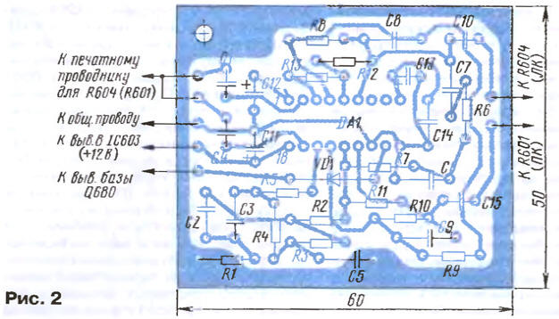
It should be borne in mind that the protective diode VD1 is introduced in order to apply a control signal exceeding the permissible level 5…V. 6 Instead of two capacitors C1 and C4 can be set, but then you need to connect together pins 2 and 17 of the chip DA1.
Fix PCB mounted in any convenient location inside the TV on the plastic ribs or protrusions of the housing near the chips on the Board the TV, which are described above.
Don't be too hard (if specified in the beginning of the article conditions) embed the device, and in other models of TVs, both domestic and imported. The control signal can serve a variety of voltage the inclusion of this or that mode, all depends on the TV set functions. If you manage to use more and the pin 12 of the chip DA1, stereo TVs will be able to work in the "Expanded stereo".
The introduction of TV pseudopterygium allowed us to obtain quite unusual surround sound.
Literature
Author: I. Patchin, Fokino Bryansk region.