


")

Additional radio control УSW, stereo amplifier and lighting
One of our authors decided to add features to your old TV, which was already installed advanced remote control system. In the result is the same remote, it can control not only themselves TV, and built-in radio receiver УSW, and stereo amplifier with stereo radio decoder, and the lighting in the room. As he did, and told in a published article. If in the future the TV to provide demodulator - decoder NICAM signal, can be taken and stereo sound television programs, already begun, and in Both Ukraine and Russia. Hams opened a large field of creativity in this direction.
In recent years the modernization of TVs third or fourth generation, constituting a very large part of the Park from the population, paid and continues be given a lot of attention mainly for economic reasons. After all after you install the remote control system (sdes), all-wave selector channels and block colour on the latest items can be quite modern apparatus at relatively low material costs. This way aimed at implementing features that already have modern models. However, there may be" another option is the introduction of new consumer features which modern TVs do not have (or already is another question). About modernization in this direction will be discussed. Although the input function quite simple, the main thing - to start.
Additional modernization undergone TV "Electron - CD" with previously set SDU with remote controller RC-6. Suggested an improvement no the majority of old TV's inputs and outputs AV, why one of a control output of the CDS were free. So I had the idea to apply its for switching any loads. In order for there were several, additionally, to manage the used voltage switching take a TV sub-bands (l-ll - VHF-1, III - VHF-3 and IV-V - UHF). In addition to keeping all the features like TV, newly introduced in device units allow you to control the power of the keys of the two loads, the parameters of one of them, and also built-in radio receiver УSW.
If the load management can be attributed to new features of the TV, then combining it with the radio УSW - haven't really forgotten old. Radio reception on УSW was implemented in produced in 50-ies TVs with separate TV sound and image "North", "Ray", "Zenit" and so on Later models combined channel used for this purpose, the second local oscillator ("Record", "Banner", "ruby") or a separate receiving unit УSW FM stations ("Temp 3", "Ruby-102", "Start-3"). Then the way radio and television dispersed. However modern portable TV reception radio stations yet provided.
As for loads, one of them is an emergency lighting with the possibility of remote or manual turn on or off. Second load - external stereo amplifier with sound stereodecoder signal. Through it you can listen to the speaker as a sound support TV and stereo broadcasts of radio stations УSW. Modes remote control volume and mute. If necessary, you can enter remote control voices with bass, treble and balance. Loads can be controlled regardless of the operation mode of your TV: readiness (SB-standby mode), television or radio broadcasting stations УSW.
When applying the mains voltage and the load are set to the off state, and the TV is in standby mode. In this mode, you can manually (not remotely) to enable or disable the load and to enable the unit in TV mode admission. It is provided for the case when, for any reason impossible to control with the remote control. Welcome УSW will be absent, as indicated by the the need for changing batteries or repair console.
With proper control the transition of the apparatus from the SB mode is provided in the working in the usual way, as provided in the RMS, However, the first mode is switched on radio reception УSW. It can be manually or remotely in advance to choose programmed station and to use all functions of the CDS: automatic tune to stations with subsequent remembering, mute, the use of a timer, accurate tuning to the station, volume control, etc D. broadcasts on the internal amplifier 34 and dynamic head, and through the external stereo amplifier with stereodecoder and sound system. When remote or manual turn on an external amplifier internal off.
Switching to the mode for receiving television programs happens when clicking the AV button on the remote control. After pressing the TV key in this mode implements all under SDU staffing functions. Mode is provided as SB usually.
Connection diagram of the modules of the device represented in Fig. 1. Modules remote control (RC) and standby (DR) are included SDU and used with minor modifications (more about that later).

Manufacturing be the modules for control and switching, as well as power modules, located in electrical outlets. Chain connector XS4 management module connected in parallel to the respective circuits of the control module of the CDS the other Two plume the control module is connected to the controlling module and the switching. All the connections are made flat cables (ribbon cables).
Schematic diagram of the control module shown in Fig. 2. Channels switching loads made the same way. Their functioning is as follows. The signals of the UHF or VHF-3 for the other channel and arrives at the AV inputs of the element DD1.1 and DD1.2. Consequently, as a result of these elements, the selection of the necessary the channel is provided by a UHF or VHF signals-3, and switching of loads - the AV signal. For manual control of loads used elements DD1.3 and DD1.4, respectively. The mode of operation of the loads (on/off).off.) determined by the state triggers DD3.1 and DD3.2. Initial installation when you turn on the power occurs through a chain C5R15. Through the power amplifier transistors VT2 and VT3 control signals pass to the thyristor power modules optocouplers.

Channel switching television or radio reception is assembled on triggers DD2.1 and DD2.2. When the signal is VHF-1 at the D input of flip-flop DD2.1 and the advent of the AV signal at the input starts With a single-shot made on the trigger DD2.1 with the reset circuit R12C2. The pulse generated by the single-shot affects the input of the trigger DD2.2, and switches the modes of reception. Manual switching occurs at the input S of the flip-flop DD2.1, and the initial installation - input R of the flip-flop DD2.2 chain C6R14. Moreover, this circuit is connected to the output of the control module, the control device is, so when you turn off the unit switches to radio mode and immediately turns off the transistor VT1.
In SB mode to the base of transistor VT1 module with remote control comes opening voltage, therefore, the transistor is open, the circuit Rx-enable receiver УSW closed and he's not works.
Consequently, the mode select with the remote control installing the necessary sub-band UHF, VHF-3 or VHF-1 (i.e., one of the programs of each sub-band), and then press the AV button and commute, or load, or a television receiver. Included subband indicated by LEDs HL1-HL3 on the front panel of the module. In the SB mode, the HL3 led glows "dimly". Structurally, the LEDs are also buttons for manual shifting modes.
Direct control of a power supply device is provided a switching module, schematic diagram of which is shown in Fig. 3. On transistor VT1 is assembled the key controlling network relays in the module ETC.

The emergence of TV signal triggers the key and connect the TV to the network, resulting in the reception of television programs. Mode radio reception УSW the device is powered by a transformer module ETC. In this case a constant voltage of about 15 V is supplied to the key, transistors VT2 and VT3. When the signal is Fix turn on the radio, the key is opened and the voltage is held on the stabilizer DA1 and the key to the power amplifier 34 to the transistors VT4-VT6. Simultaneously, the transistor VT3 is provided to lock UPCS TV. With stabilizer DA1 voltage of 12 V comes to the control module (via connector XS1), the control module and UPCS TV. The state of the power key amplifier 34 is determined by the operation mode stereo amplifier load 1. If the load is enabled, the key is closed and the internal amplifier 3H TV de-energized.
The module power control must be ensured as in the TV mode, and the radio mode, therefore, the power supply circuit of obyedinenie diodes VD3 and VD4. A similar solution is provided in the circuit configuration with a supply voltage of +31 In (diodes VD5 and VD6). But it was assumed the use all-wave channel selector of the TV as the input device for the receiver УSW, and the last would be configured at the if sound. So could to take not only the radio but the sound is all television programs. For this purpose it is necessary voltage settings +31 In, and why were imposed voltage multiplier with stabilizer elements C3, C4, R12, VD7-VD11 and the AGC circuit R5R6VD2. In the final version from the author this possibility was rejected, so these elements shown by dashed line (they are not installed). Anyone can do this by setting in the TV the all-wave channel selector instead of a separate meter and decimeter.
The voltage settings for the radio are submitted via the jumper W1 and the diode VD6 with stabilizer DA1 and equal to, as specified, and +12 V. It is quite enough to overlap broadcasting range УSW.
The device used is a standard module PD is modified by the circuit of Fig. 4. The improvement consists in installing a more powerful transformer T1, capacitor C1 filter larger capacity, the connector on the four pins and the connection circuits according to the scheme. You can use the transformer TCE-LM on lamp TVs.
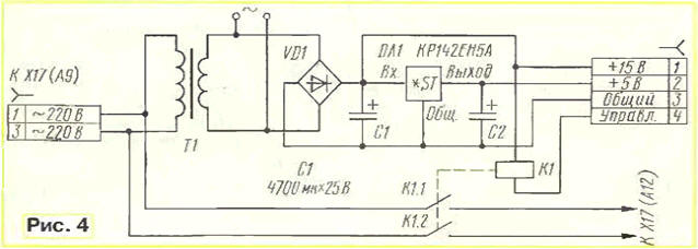
Power modules are collected by the same scheme presented in Fig. 5, and features do not have. You only have to recall that the triacs TS-10 release until the mid 90-ies have the Pinout from the inscriptions UE, 2(A), 1(K), a later - 1(K), 2(A), Oued.
Changes in blocks and modules of the TV are as follows.
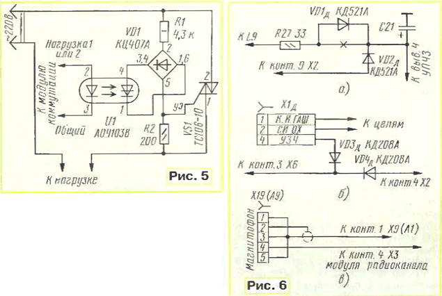
In submodule of a radio channel, you must set pin 9 on connector x2 (refer to connectors in accordance with the scheme of the TV). The required changes in submodule to perform according to the scheme in Fig. 6,and. So to ensure the food UPCS.
The connection Board (except PS-50) placed the four-pin connector, soldering it to the printed conductors leading to the contacts 10 and 11 of connector X4. Then collect the node according to the scheme in Fig. 6,6. Diode VD4Д solder instead of jumpers, connecting pin 4 of connector x2 and pin 3 of connector X6. Contacts 1, 2 installed connector is connected to the corresponding circuits of the control module. In the result of this synchronization occurs SDU and the internal power amplifier 3H TV.
On cross-Board radio module connector set XS, if, of course, no. Next, connect pin 2 of the connector XS with the contact 9 of connector x2 (power UPCS), contact 4 of connector XS - 6 contact connector X9 (adjustment volume), and pin 16 of connector X1 - through diode KDA (anode to this contact with the pin 10 of connector x2 (APCG).
Connector X19 "tape Recorder" unit A9, used to connect stereo amplifier, raspalaut as shown in Fig. 6,V. the contacts will 1,3,5 to attend the audio signal (CSN), and the contact 4 - voltage control volume. Respectively must be unsoldered and the input connector a stereo amplifier. In the author's version in the input stage of the amplifier applied chip TDA1524 and stereodecoder - TA.
To control the voices and the balance you can use voltage control brightness, contrast and saturation.
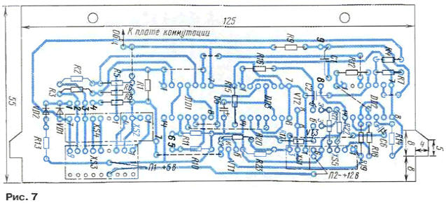
Structurally, the device is made of two printed circuit boards of one-sided foil fiberglass. Drawing printed conductors and the location elements on the circuit Board of the control module shown in Fig. 7. Connectors XS4 and XS2, and also XS1 and XS5 made in pairs as a single unit. Socket XS3 selected parallel with relative to the Board position of the contacts, so the payment to the radio when УSW connecting to it is a continuation of the Board of the control module.
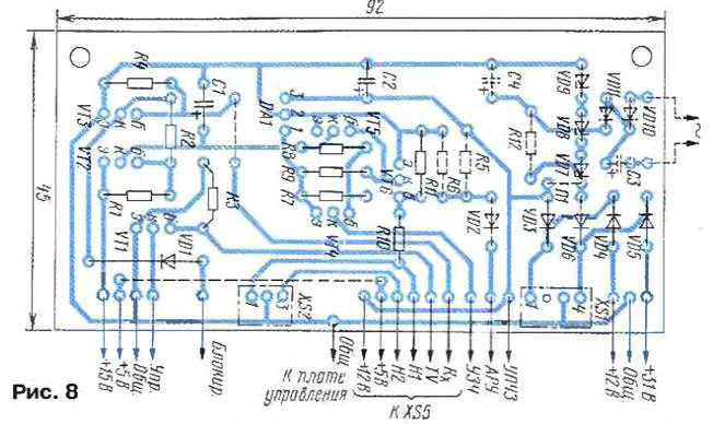
Drawing printed conductors and the placement of the parts on the module Board switching presented on Fig. 8.
On-Board management module installed l-shaped plastic panel (dimensions: width - 90, height - 25cm, depth - 10 mm), which on the racks and stripes tin fixed microswitches MP7 - button SB1-SB3 with capacitors C3 ( SB1) and C4 (SB2). The findings of LEDs wearing plastic blocks, and the findings are bent to the side at a right angle. Clicking on each led the cubes act on the rod microswitch. The module is inserted into the front TV panel instead of the tuner USU-1-15.
Modules DC and switching fixed on the side wall inside the TV is about network enter.
Power modules are small in size and are, as was said, in electrical outlets are square shaped. With the device, connect them via miniature plugs. Three sockets - two for the load and one network for the TV in one unit.
In the device instead of transistors CTG and KTV you can use any low-power silicon transistors. Instead of transistors applicable CTB transistors series CT or CT, preferably with minimal voltage drop collector-emitter, for example, CTF.
The connectors used are the same as in TV, the deficit, they are not.
In establishing the device does not need. It is only necessary to equalize the levels signal 34: in TV the resistor R11 of the unit radio channel, and the corresponding controllers in an external stereo amplifier and radio УSW, so that when you change modes, no volume changes.
In the TV applied SDU processor INA84C641NS-168. The control signal the inclusion of the apparatus is transmitted from the processor via the chip, the output of which installed a transistor with open collector. In the SB mode, the transistor is closed. The AV signal has a level of about 5 V, the signal TV - 0. Remote control - RC-6.
Now you have to say about the radio УSW. In the author's version used the simplest receiver range УSW-2 (88… 108 MHz) on-chip CHA, assembled under the standard scheme. It provides direct set, i.e. increase the voltage setting rebuilds heterodyne upward toward more the high frequencies. Antenna pigtail is a length of about 40 cm, located inside the TV.
Connector to connect the receiver removed all the pressure switching sub-bands, so the radio can make a multi-band. Appointment the connector pins clear from their labels. The power of radio can be 5 or 12 V. depending on the required supply voltage connect the jumper (P1 or P2) one or the other pair of contacts that are marked on the PCB module management.
If your TV has applied SDU that allows you to manually set and memorize station, the output APCG module do not connect. This will work The AFC of the receiver.
It should be borne in mind that the voltage settings in the original is changed from 0.5 to 10 V. Therefore, it is necessary or voltage divider, or a capacitor, included in series with the varicap, to set the boundaries of accepted range УSW.
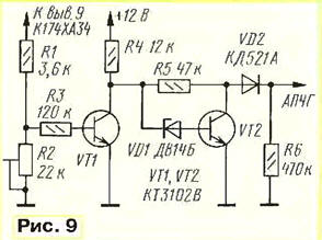
In addition, in the embodiment of the author of the CDS made on a simple scheme, i.e. without channel stop, and the input IDENT CPU constantly enjoyed a voltage of +5 V. Also you have not implemented the ability to manually adjust with memory, so the radio is supplemented by a simulator capture station, collected by the circuit Fig. 9. Resistor R2 sets the best sound quality when capturing station.
Receiver Board is fixed on the segment of the standardized circuit Board to which soldered the necessary contacts for connection with the XS3 connector of the control module device. On the same circuit Board soldered parts simulator capture.
Author: G. Alekhin, Donetsk, Ukraine