Many families still operated televisions obsolete brands - ULCT, OPENCT and even USCT. Their the owners, having experience in Amateur radio design, would like to give owned vehicles number of possibilities inherent in the new modern models, to improve the quality of the received image and some parameters. In this article explains how you can improve your old TVs, using chip TDA8362.
Mass production of color TVs in our the country began in 1973 with the release of a standardized tube-semiconductor model WPCT in the future - OPCT(S) replaced which series came UPONST in the future - USCT and USCT. Their annual the best release in years exceeded two million units. Although in 1991. appeared the apparatus of the fourth generation, the bulk of production to the last years was a TV USCT. No wonder that after the collapse of the USSR in residents of Russia have more than 40 million color TVs mainly the first to third generation. All of them, from the point of view of modern user are considered outdated morally and physically.
If the question is about the moral aging of the apparatus is clear, something about their physical aging can be seen if we remember that the age the surviving population of TVs OPCT reaches 20...25 years discontinued in 1978). TVs same OPENCT (age 15 20... years), there are 5-6 million Finally, Park USCT is now 20-25 million. instances with age from 5 to 20 years. By pre-existing norms of the period service TV has been set to 15 years. From this point of view, all devices ULPORT, OPENCT and part USCT already served and their needs seem to concede place to new.
However, in the magazine "Radio", and in another the literature still appear article with suggestions on upgrading old TVs. And that's good. On prolonging their lives can and should think. This is necessary because the financial situation of many families does not allow them to replace your existing TV with a new one. Besides at least 10-15 million USCT not fulfilled the due date and can still serve their owners. All this suggests that the problem of modernization of TVs for the purpose of extending life, increasing reliability and the introduction of new functions in low cost (no more than 20% of the cost of a new machine) - very relevant and remains so more than one year.
One way to resolve this problem call introduction to older TV sets modern element base. But before turning to the specific proposals refer to a little history.
Integrated circuits in domestic TVs were first used in 1976. in one of the zi models WPCT(AND), which was used by a module chromaticity of BCI on chips series C. Wider application of the chip found two years later in TVs OPENCT when the electronic industry mass production series C. Early devices had a low degree of integration and needed a large number of external electronic components. So, ten ten circuits in the block signal processing (SPU) of TV OPENCT was accompanied 440 different details. By modern standards, it's too much for a radio channel and channel chroma.
In published here table summarizes information about the number of parts in blocks of radio, sync, color and output the video amplifiers of TVs of different generations. It follows from that position improved somewhat with the advent of TVs USCT and USCT, which were applied better chip series C.
Generation of TVs The number of chips The number of external elements The number of points settings Just Including transistors resistors trimmer resistors regular capacitors oscillatory circuit OPENCT 10 440 35 195 17 155 22 39 USCT, USCT 6-7 300-330 16-21 150-155 13-18 95-125 7-8 21-26 USCT 6 280-320 8-9 100-130 10-12 105-120 10-12 20-24 5-6 generation
with TDA8305/4504
with TDA8362
5-6
3-6
340-350
160-170
24-25
3-14
155-160
70-75
6-7
4-5
125-130
60-70
12
1
18-19
5-6 USCT with MRCC 7 180 7 85 7 78 1 9
However, the number of hinged parts remained still large, which reduced the operational reliability of these most massive TVs. Reliability is also reduced a large number of bodies adjustment to adjust during production and after repair and the presence of two dozen pairs of interconnect connectors with hundreds of contacts. No accident TVs the fifth and sixth generations have clearly been a trend towards the use of chips high degree of integration, allowing for the expansion of the list of functions to save and how to reduce their number and the composition of the external frame, to reduce the number of items (points) of adjustment. From the many connectors now get rid of, refusing cassette-modular design and returning to the monoblock chassis - based the first industrial and Amateur TVs. Where connectors from you cannot opt out, apply them to a new, more reliable model.
As for the chips, TVs the fourth and fifth generations of the paths of the radio channel and the chroma is still contain five or six buildings and require the same number of hinged parts that and models of the third generation. Against this background, stand out for the better multi chip Philips allows in TVs sixth generation to solve circuit problems more efficiently and to implement radio channel and tract chroma on three buildings while reducing external frame twice. These include BIS TDA8362, TDA8375, TDA8396, which is the most widely used first. It is used not only leading foreign firms (for example, a Panasonic TV-TX-21S, etc.), but also in the CIS ("Horizon-CTV-655", "Electron-TC-570/571", "TVT-2594/2894"). Some models use three to six chips, that explains the use of integrated video amplifiers, diffusing less power and reducing the number of transistors from 14 to 3.
Of course, the chip can be TDA8362 used in TVs and outdated models of modernization (replacement blocks of a radio channel, chroma and sync more sophisticated).
Detailed description of the structure and operating parameters chip TDA8362 given in [1] and [4]. It provides a signal processing black-and-white and color television as intermediate frequency (if) and filed in the form of chroma and color signals encoded according to the system SECAM, PAL, NTSC. In this case the frequencies may have, as usually used in negative modulation, and used in the French standard L positive. Video signals can be presented in the format of VHS and S-VHS. In addition, it handles frequency-modulated sound signals according to the standards of M (4.5 MHz), B, G, H (5.5 MHz), I (5.996 MHz), D, K, L (6.5 MHz) and audio signals CC and signals horizontal and vertical synchronization (the latter at frequencies of 50 and 60 Hz) when the number of lines per frame in the range of 488...722.
Implementation of all these functions in a single chip achieved using conventional bipolar transistors for processing analog signals of any frequency and transistors of MOS structure for solving digital methods.
There are several modifications of the chip, the distinguished list of implemented functions and Pinout. Full potential in all these functions are provided in TDA8362A, but modifications and TDA8362 TDA8362N3 much cheaper, but have minor differences.
Analysis of the possibilities of the chip TDA8362 shows that their use in full volume in our environment and not required. Many find it overkill the ability to handle NTSC signals, because essential programs encoded in NTSC-M 3.58 unavailable to our audience (except living on the Chukchi Peninsula and the South of Sakhalin). Processing signal system NTSC-4.43 might need only when you view the records on the videotapes and DVDs made in the USA, Japan and Korea. Certainly not required, and the reception signals in the standards H, I, and signals positive modulation standard SECAM-L. However, the work on these standards (H, I, SECAM-L, NTSC-4.43) is already provided in the chip TDA8362 and to give them not only not to use them.
Probably for these reasons, in [2], the typical operating circuit modification TDA8362A to process only signals systems SECAM, PAL and standards B, G, D, K. harmony with them, and invited hams to the module channel, chroma and synchronization (MRCC) on the chip TDA8362 adapted for use in TV USCT any model. Will also be given recommendations for those wishing to introduce the features module receiving signals system NTSC-4.43 and use of the module in the other types of TVs.

Module MRCC replaces in TVs USCT modules radio (A1) and chroma (A2) with submodules SMRC (A1.3), SRM (A1.4), SMC (2.1). cassette-the modular design of the chassis of TVs simplifies USCT work on replacing the modules, reducing it to the removal of the two boards and install them place new. The module is powered from available TV sources of stress 12 and 220V. Current consumption of the circuit 12B equal mA (instead of at more than 500mA replaceable modules), which beneficially affects the operation of the rectifier in the power module of the TV and reduces power consumption.
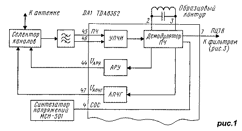
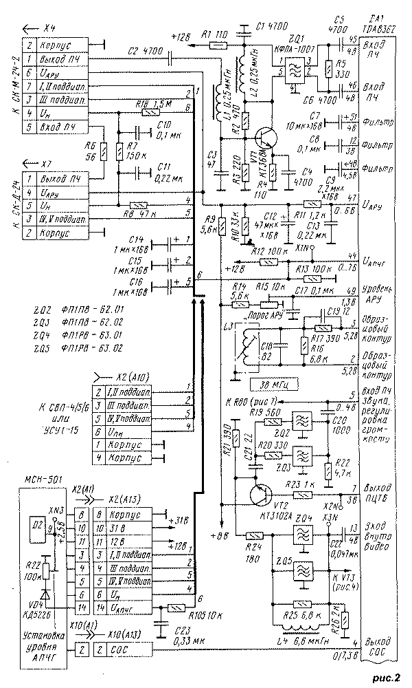
Consider the schematic diagram of the module, starting with his radio. It includes the channel selectors, preliminary amplifier with saw filter, UPCI, the if demodulator, the device APCG and ARU. Block diagram, showing the interconnection of these blocks is depicted in Fig.1. In Fig.2 is a schematic diagram of the tract. Depending on the device type selection programs (CIP) the diagram shows connectivity options blocks USU-1-15 (SVP-4/5/6) and synthesizer, the sit-501 (drawn thick lines).

The sensitivity of the chip TDA8362 (DA1 at Fig.2) at the input (pins 45 and 46) is equal to 100 µv, and according to the existing norms the sensitivity of the television in the sub-bands I, II should be no worse than 40 µv on the antenna input. Consequently, the transmission coefficient (gain) Ku in the circuit from the antenna input and the input chips should be at least 8 dB. The circuit comprises a channel selector SC-M-24 (RL=15 dB) and a saw filter ZQ1 (Ku < -25 dB). This means that when direct connection of the selector to the filter input sensitivity of the TV will be below normal to not less than 18 dB (approximately 320 mV), which is unacceptable. For its conservation incorporated preliminary amplifier transistor VT1 c RL > 20 dB, allowing a small margin to compensate for the attenuation in the filter ZQ1.
By the way, Ku modern all-wave selector UV-917 Philips equal to not less than 38 dB at very low noise level that allows you to directly connect it with filter surfactants and provide the increased twofold sensitivity TV. The selector used in the TV "Horizon CTV-655".
Bandpass filter must meet ZQ1 the following requirements: to work on a carrier FC image 38 MHz, have wide horizontal section frequency response ("shelf") in the band 31.5 32.5... MHz and balanced out. These requirements are met by saw filters CFPA-1007, CFPA-2992, CFPA-A. Widespread filters CFPA-1008, KFE have a narrow "shelf" and will not ensure admission standards B, G. the Filter FPSP-451, used in TVs USCT, has unbalanced output, which requires the introduction between him and chip balancing of a cascade of two transistors.
After amplification in UPCI (see Fig.1) the frequencies in the demodulator is converted to a full color television video signal (PCT). The demodulator contains a node inversion of white spot (limit emissions PCTV caused by noise) at the level of the average brightness, which improves image quality, preventing the appearance of clutter on the screen, as well as sharp the change in the amplitude PCTV and its clock.
Oscillating circuit L3C18 (see Fig.2) is General exemplary demodulator circuit for the inverter device APCG that reduces the number of setting items in the module. Voltage APCG (UАПЧГ) on checkpoint X1N in the capture of the signal may vary 0.5 6.3...and In the fine tuning circuit to the frequency of 38 MHz and the selector the carrier image is equal to 3.5 V.
When using a DIP-type CCA, voltage MRAs UАПЧГ is supplied to the selector circuit R12R13R18C10R7C11, where it merged with the preliminary voltage settings UПН that come with using UVP resistor R8, forms a voltage configuration selector ULO. In the case of the use of synthesizer stresses the sit-501 summation of voltages UАПЧГ with UПН and the formation of the UN occurs in the synthesizer. Voltage UАПЧГ served on him by the chain R12R13R105C23, and the obtained value u n runs on selectors from pin 6 of connector X2 (A13) on the chain R8C11R7C10.
Back to the exemplary circuit L3C18. For each TV is such a feature characteristic: in the preliminary process settings on any program open the device APCG it turns out that the swath image carrier when you approach her with the low-frequencies is wider than the same band when configuring with the higher frequencies. This phenomenon occurs not from a bad adjustment APCG. It is because the image carrier when properly configured selectors located on the slope of the frequency response of a bandpass filter FC (no matter it will be a saw filter in TVs USCT or filter centered breeding in OPENCT). The slope leads to the asymmetry of the signal supplied to the demodulator device APCG, especially noticeable in low the input signal is smooth when at the input of the channel selector noise becomes markedly asymmetric at the input of the system APCG. As a result there is a voltage shift from UАПЧГ the correct values, which causes a detuning of the receiver and specified the asymmetry of the swath. When you use a chip taken TD8362 measures to eliminate such defect switching circuit C19R19.
The voltage of the IARU served on the selector channels with output 47 of the chip through the circuit C13R11C12R10R9. The initial level set trimming resistor R15.
From pin 4 of the chip to pin 2 of the connector X10 (A13) receives the identification signal synchronization (COC) used in the synthesizer voltage control system auto-tuning programs. The voltage signal equal UСОС zero, if the input circuit has no clock pulses. Voltage The UСОС equal to 6, if the input comes signal system NTSC 3.58, or * if you are receiving a "color" or black and white signal systems SECAM, PAL, NTSC-4.43.

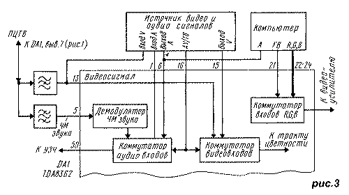
From pin 7 of the chip PCTV arrives on set external filters, where it is separated into the video signal and the FM audio signal. Bandpass filters ZQ2, ZQ3 allocate bandwidth hosting FM signals sound (5.5 +/- 0.05 MHz in the standards B, G and 6.5 +/- 0.05 MHz in the standards D, K). Via pin 5 of the chip they are as shown in Fig.3, pass to the demodulator and then to switch audio inputs. The FM sound demodulator has a phase-locked loop (PLL), that auto-adjust to any standard audio support.
Notch filters ZQ4, ZQ5 (see Fig.2), cleaning PCTV from bands occupied by the FM signals sound, turn it into a video signal, through which the pin 13 of the chip is supplied to the switch inputs (see Fig.3). In Fig.3 shows the switch R, G, B, his work consider further.
To switch audio and video inputs come signals from external sources (VCR, player VCD, games a video game console). Control switches (function AV/TV) is provided by filing the appropriate voltage on pin 16 chips: less than 0.5 for inclusion In the essential programs (TV); 3.5...5 V for enable external program format S-VHS (AV); 7.5...8 In to work from external source format VHS (AV). If the voltage at pin 16 no, the chip operates in TV mode.

Recall that recently appeared the tape format S-VHS (for example, Philips-VR969) provide a more high quality image (400-430 lines against lines 230 to 270 VCR format VHS and 320...360 lines of essential programs). This is achieved by placing color components are not in the regular lane 3...4.7 MHz PZT, and in the band...7 5.4 MHz. When playing such VCRs are connected by three chains: the audio signal on pin 6 chips, the brightness signal S-VHS Y - on pin 15, the chroma S-VHS-C - on pin 16.
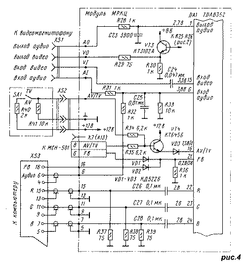
If there is only one external source video in VHS format, it is connected to MRCC as shown in Fig.4. When using the synthesizer of the sit signal AV/TV comes from him through connector X7 (A13). If applied blocks CCA, MRAs, it is possible to receive the signal AV/TV have to manually switch SA1 has two positions, installed in convenient location of the TV. In both cases, the TV mode is formed voltage is not more than 0.4 In (or if it is missing), and AV mode is not less than 10 V. Last transferred to pin 16 of the chip through the switch transistor VT4.
The type of input and output connectors XS1, XS2 choose depending on the type of their return in the used parts source signals.
If you have multiple video sources, they are connected to MRCC through a matching unit. Detailed information according to the construction given in [


