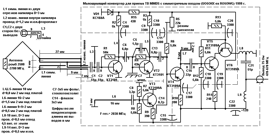
This Converter is designed to receive TV MMDS on a simple rhombic antenna. The symmetry of the entrance is provided with two lines. The first is formed by two segments of copper tube 3 mm in diameter (capillary), with a gap of 3 mm between them, closed at one end (soldered to the side wall of the box). The second line is located coaxially inside one of capillaries and is made of copper wire 1.2 mm in diameter and insulated PTFE tape wound on him. Through the hole in the capillary it using the strap connects with the second capillary.
After coordination, the movement of the clamp, it is fixed to the capillary soldering. These lines together are transforming the high impedance of a rhombic antenna units in Ohm input impedance of the transistor VT1. Capacitors C7 and C14 constructive. C7 made of 1.5 mm double-sided fiberglass size 3x5 mm and soldered between the base and VT2 channels. C17 the box is made of tin, 3x3 mm to bend and 2x7 mm pripiski, located near emitter output resistance R9. Adjustable connection check box C14 and podstroechnik R5 is set to the optimal mode mixer VT4. The frequency of the local oscillator VT3 is set by the flexion line L6 to "earth". Transistor KTA in the local oscillator is not a mistake, as it turned out, he easily generates frequencies up to 2500 MHz! All parts fully connected feed-through capacitors, located in the basement on the other side of the Board. Cm. "Completion of walk-through capacitors". Supply voltage +12 V is supplied through the signal cable through the LC filter similar L9C21 Converter. 73! UO5OHX ex RO5OWG 1999, rhombic antenna, see here.

Author: E. shoustikov, UO5OHX ex RO5OWG; Publication: www.shustikov.by.ru, www.cxem.net


